Buick Encore: Component locator
DISASSEMBLED VIEWS
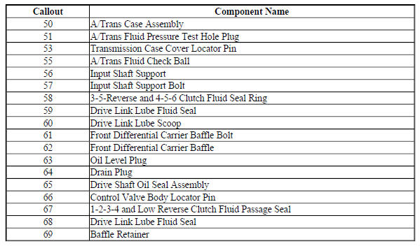
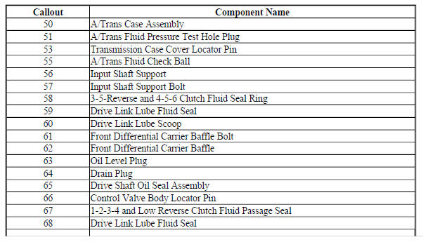
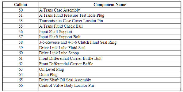
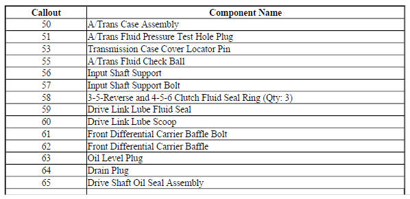
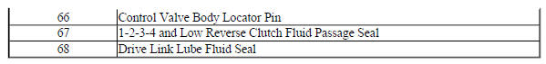
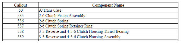
Case and Associated Parts
Fig. 1: Disassembled View Of Case & Associated Parts
Transmission Case Assembly - 6T30 - Gen 1
Fig. 2: Transmission Case Assembly -- 6T30 -- Gen 1
Transmission Case Assembly - 6T30 - Gen 2
Fig. 3: Transmission Case Assembly -- 6T30 -- Gen 2

Transmission Case Assembly - 6T40/6T45/6T50 - Gen 1
Fig. 4: View Of Transmission Case Assembly

Transmission Case Assembly - 6T40/6T45/6T50 - Gen 2
Fig. 5: Transmission Case Assembly Components -- 6T40/6T45/6T50 -- Gen 2
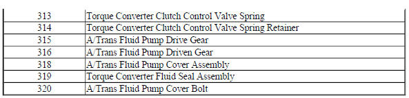
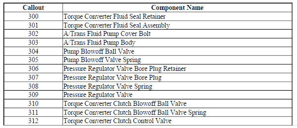
Torque Converter and Fluid Pump Housing Assembly- 6T30

Fig. 6: Torque Converter and Fluid Pump Housing Assembly -- 6T30
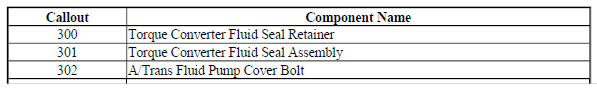
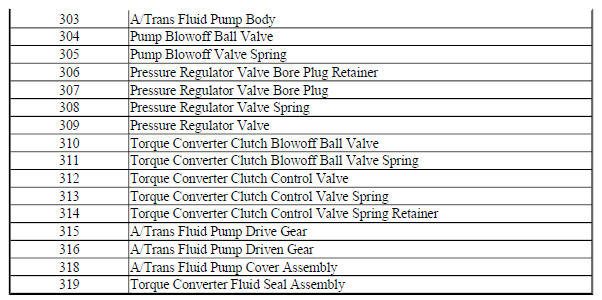
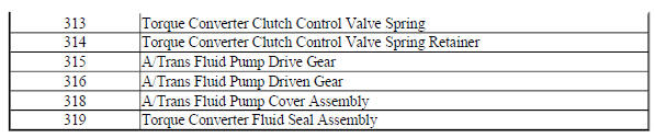
Torque Converter and Fluid Pump Housing Assembly- 6T40/6T45/6T50
Fig. 7: Torque Converter and Fluid Pump Housing Assembly Components --
6T40/6T45/6T50 -- Gen 2
Drive Link Assembly
Fig. 8: Disassembled View Of Drive Link Assembly
Oil Pump Assembly- 6T30
Fig. 9: Oil Pump Assembly -- 6T30

Oil Pump Assembly- 6T40/6T45/6T50- Gen 1
Fig. 10: Disassembled View Of Oil Pump Assembly
Oil Pump Assembly- 6T40/6T45/6T50- Gen 2
Fig. 11: Oil Pump Assembly Components -- 6T40/6T45/6T50 -- Gen 2
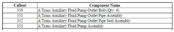
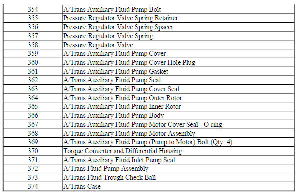
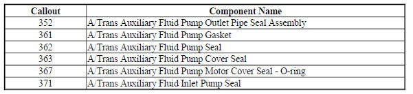
Auxiliary Fluid Pump and Hybrid Components - Hybrid Models
Fig. 12: Auxiliary Fluid Pump and Hybrid Components -- Hybrid Models
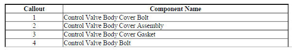
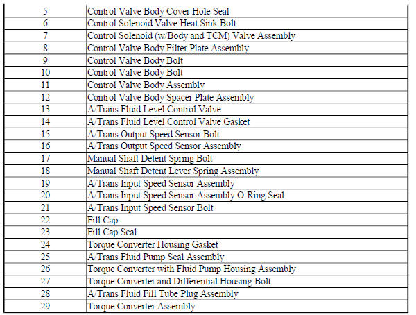
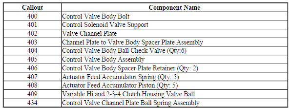
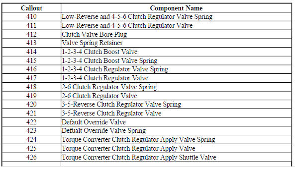
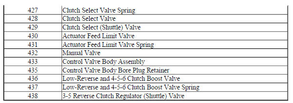
Control Valve Body Assembly (1 of 2 - Gen 1)
Fig. 13: View Of Control Valve Body Assembly (1 Of 2)
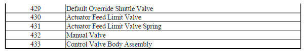
Control Valve Body Assembly (2 of 2 - Gen 1)
Fig. 14: View Of Control Valve Body Assembly (2 Of 2)
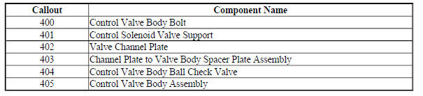
Control Valve Body Assembly (1 of 2 - Gen 2)
Fig. 15: Control Valve Body Assembly -- Gen 2 (1 Of 2)
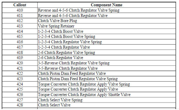
Control Valve Body Assembly (2 of 2 - Gen 2)
Fig. 16: Control Valve Body Assembly -- Gen 2 (2 Of 2)
3-5 Reverse Clutch Assembly - Gen 1
Fig. 17: View Of 3-5 Reverse Clutch Assembly
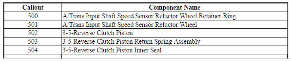
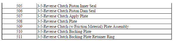
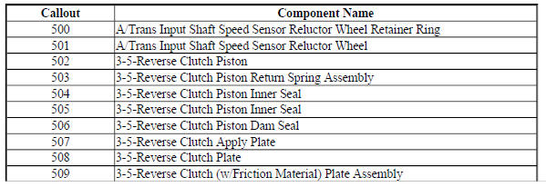
3-5 Reverse Clutch Assembly - Gen 2
Fig. 18: 3-5 Reverse Clutch Assembly Components - Gen 2

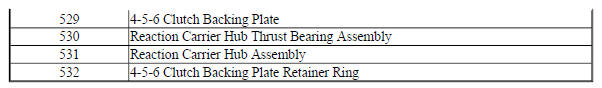
4-5-6 Clutch Assembly - Gen 1
Fig. 19: View Of 4-5-6 Clutch Assembly
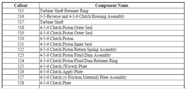
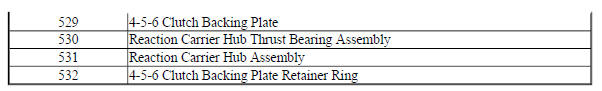
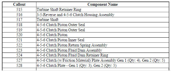
4-5-6 Clutch Assembly - Gen 2
Fig. 20: 4-5-6 Clutch Assembly Components -- Gen 2
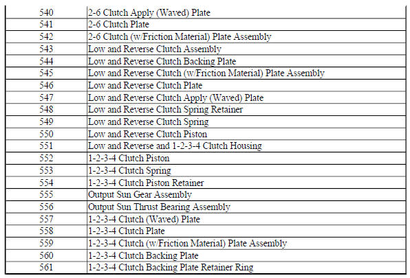
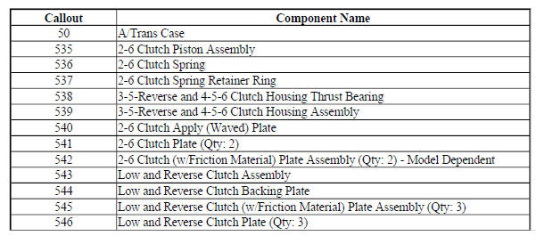
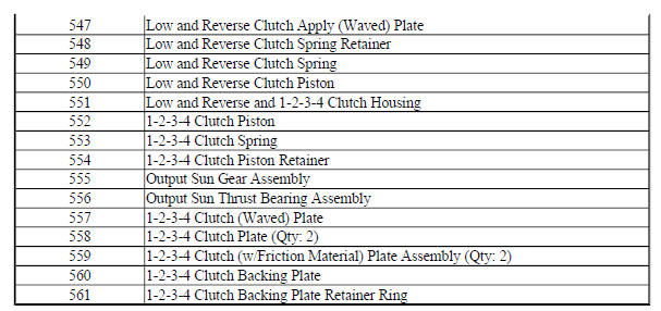
2-6, Low and Reverse and 1-2-3-4 Clutch Plate Assemblies - Gen 1
Fig. 21: Disassembled View Of 2-6, Low 7 Reverse & 1-2-3-4 Clutch Plate
Assemblies
2-6, Low and Reverse and 1-2-3-4 Clutch Plate Assemblies - Gen 2
Fig. 22: 2-6, Low, Reverse And 1-2-3-4 Clutch Plate Assemblies - Gen 2
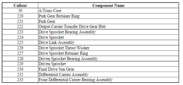
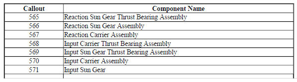
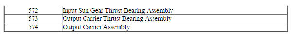
Input, Output and Reaction Gearsets- 6T30/6T40
Fig. 23: Input, Output and Reaction Gearsets -- 6T30/6T40
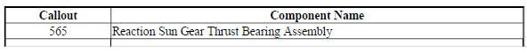
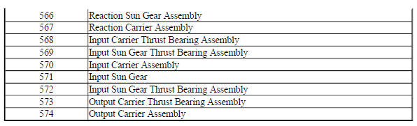
Input, Output and Reaction Gearsets- 6T45/6T50
Fig. 24: View Of Input, Output & Reaction Gearsets
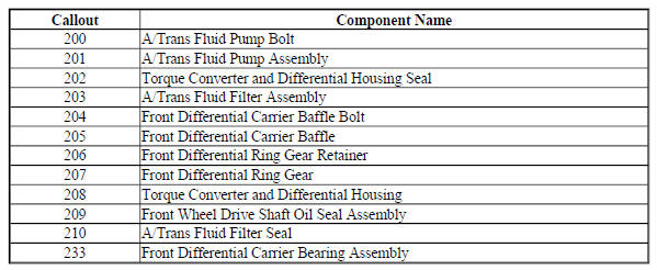
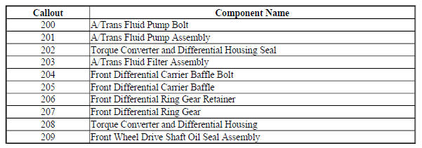
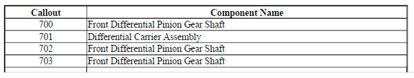
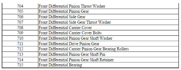
Front Differential Carrier Assembly (2 Pinion)
Fig. 25: Disassembled View Of Front Differential Carrier Assembly
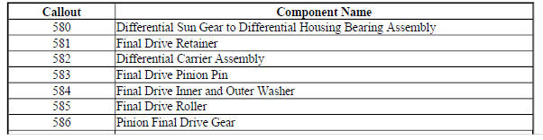
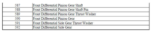
Front Differential Carrier Assembly (4 Pinion)
Fig. 26: Front Differential Carrier Assembly Components (4 Pinion)
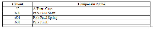
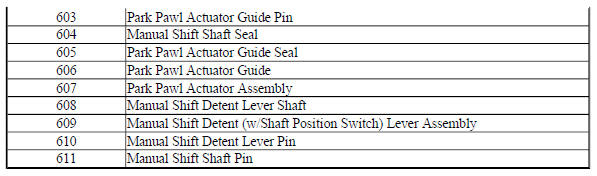
Park System Components
Fig. 27: View Of Park System Components
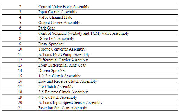
COMPONENT LOCATION
Fig. 28: Identifying Component Location

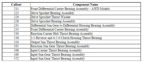
BUSHING, BEARING, AND WASHER LOCATIONS (GEN 2/HYBRID)
Fig. 29: Bushing, Bearing, and Washer Locations (Gen 2/Hybrid)

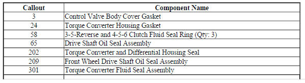
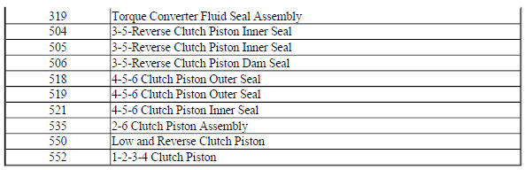
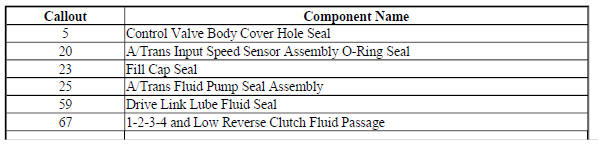
SEAL LOCATIONS (GEN 2/HYBRID)
Seal Locations (1 of 2)
Fig. 30: Seal Locations (Gen 2/Hybrid)
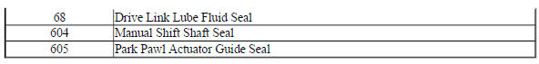
Seal Locations (2 of 2)
Fig. 31: Seal Locations (Gen 2/Hybrid)
Auxiliary Fluid Pump and Hybrid Seals - Hybrid Models
Fig. 32: Auxiliary Fluid Pump and Hybrid Seals -- Hybrid Models
BALL CHECK VALVE LOCATIONS (GEN 2/HYBRID)
Fig. 33: Ball Check Valve Locations (Gen 2/Hybrid)
Ball Check Valve Locations (Gen 2/Hybrid)
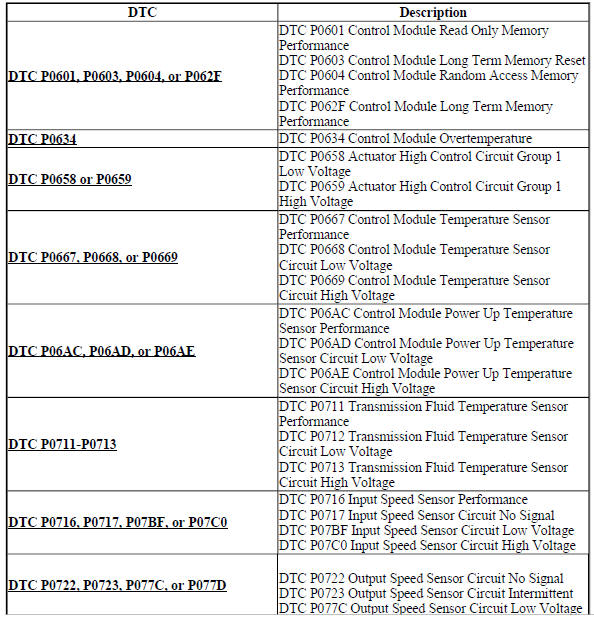
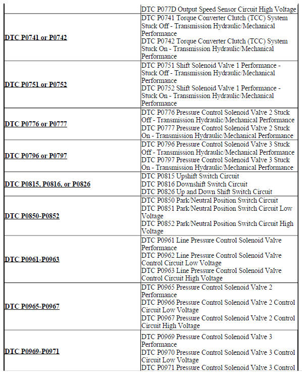
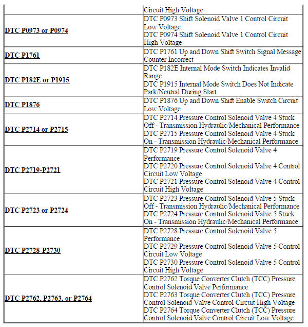
Diagnostic code index
DIAGNOSTIC CODE INDEX
READ NEXT:
 Diagnostic information and procedures
DTC P0601, P0603, P0604, OR P062F: Control module memory
Diagnostic Instructions
Perform the Diagnostic System Check - Vehicle prior to using this
diagnostic procedure.
Review Strategy Based Diag
Repair instructions - off vehicle
Repair instructions - off vehicle
Fig. 1: Identifying Lift Plate & Holding Fixture
Lift Plate and Holding Fixture Installation
TORQUE CONVERTER REMOVAL
Fig. 2: View Of Torque Converter
Tor
Repair instructions - on vehicle
Manual shift detent lever with shaft position witch assembly replacement
Special Tools
DT-41229 Manual Shaft Pin Installer
For equivalent regional tools, refer to Special Tools .
Removal Procedure
R
SEE MORE:
Luggage Rack and Roof Trim
SPECIFICATIONS
FASTENER TIGHTENING SPECIFICATIONS
Fastener Tightening Specifications
REPAIR INSTRUCTIONS
LUGGAGE CARRIER SIDE RAIL REPLACEMENT (Encore)
Fig. 1: Luggage Carrier Side Rail
Luggage Carrier Side Rail Replacement (Encore)
Maintenance and Lubrication
SPECIFICATIONS
APPROXIMATE FLUID CAPACITIES
The following approximate capacities are given in English and metric
conversions. All capacities are
approximate. When adding, be sure to fill to the approximate level as
recommended in this manual. Recheck
fluid level after filling.
FLUID AND LUBRICAN
