Buick Encore: Schematic wiring diagrams
SPECIFICATIONS
FASTENER TIGHTENING SPECIFICATIONS
Fastener Tightening Specifications
.jpg)
SCHEMATIC WIRING DIAGRAMS
ANTILOCK BRAKE SYSTEM WIRING SCHEMATICS (ENCORE)
Module Power, Ground and Subsystem References
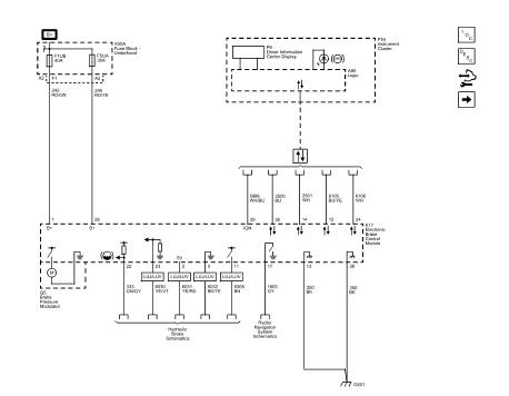
Fig. 1: Module Power, Ground and Subsystem References
Wheel Speed Sensors
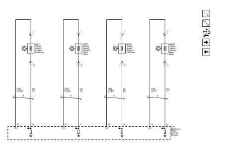
Fig. 2: Wheel Speed Sensors
Stability Control
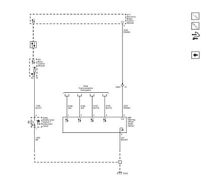
Fig. 3: Stability Control
ANTILOCK BRAKE SYSTEM WIRING SCHEMATICS (Encore)
Module Power, Ground and Subsystem References
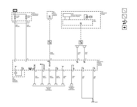
Fig. 4: Module Power, Ground and Subsystem References
Wheel Speed Sensors
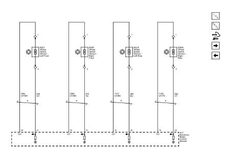
Fig. 5: Wheel Speed Sensors
Stability Control
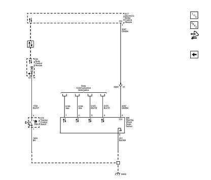
Fig. 6: Stability Control
READ NEXT:
 Diagnostic information and procedures
DTC B2745 (WITH C67/CJ2): Traction control switch
DIAGNOSTIC CODE INDEX
DTC B2745 (WITH C67/CJ2): Traction control switch
Diagnostic Instructions
Perform the Diagnostic System Check - Vehicle
Repair instructions
Antilock brake system automated bleed
WARNING: Refer to Brake Fluid Irritant Warning .
CAUTION: Refer to Brake Fluid Effects on Paint and Electrical
Components Caution .
NOTE: Before performing the A
Description and operation
ABS DESCRIPTION AND OPERATION
Antilock Brake System Block Diagram
Fig. 45: Antilock Brake System Block Diagram
This vehicle is equipped with the MGH 60 Mando electronic stability control
brake
SEE MORE:
Seat heating and cooling - Repair instructions
FRONT SEAT HEATER CONTROL MODULE REPLACEMENT
Fig. 3: Front Seat Heater Control Module
Front Seat Heater Control Module Replacement
DRIVER OR PASSENGER SEAT BACK CUSHION HEATER REPLACEMENT
Fig. 4: Driver Or Passenger Seat Back Cushion Heater
Driver or Passenger Seat Back Cushion Heater Replac
Seat Belt Use During
Pregnancy
Seat belts work for everyone,
including pregnant women. Like all
occupants, they are more likely to
be seriously injured if they do not
wear seat belts.
A pregnant woman should wear a
lap-shoulder belt, and the lap
portion should be worn as low as
possible, below the rounding,
throughout the pregn
© 2020-2026 Copyright www.bencore2.com
