Buick Encore: Schematic wiring diagrams
Buick Encore 2012-2019 Service Manual / Accessories & Equipment / Wipers and Washers / Schematic wiring diagrams
SPECIFICATIONS
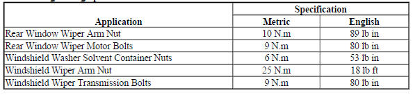
FASTENER TIGHTENING SPECIFICATIONS
Fastener Tightening Specifications
SCHEMATIC WIRING DIAGRAMS
WIPER/WASHER WIRINGSCHEMATICS (ENCORE)
Front Wiper/Washer Control and Wiper
Fig. 1: Front Wiper/Washer Control and Wiper
Rear Wiper/Washer Control and Wiper
Fig. 2: Rear Wiper/Washer Control and Wiper
Windshield Washer
Fig. 3: Windshield Washer
WIPER/WASHER WIRINGSCHEMATICS (Encore)
Front Wiper/Washer Control and Wiper
Fig. 4: Front Wiper/Washer Control and Wiper
Rear Wiper/Washer Control and Wiper
Fig. 5: Rear Wiper/Washer Control and Wiper
Washer
Fig. 6: Washer
READ NEXT:
 Wipers and Washers - Diagnostic information and procedures
DTC B370A: Rain sensor
DIAGNOSTIC CODE INDEX
DIAGNOSTIC CODE INDEX
DTC B370A: RAIN SENSOR
Diagnostic Instructions
Perform the Diagnostic System Check - Vehicle prior to using this
diagnostic p
Wipers and washers - Repair instructions
WINDSHIELD WIPER AND WASHER SWITCH REPLACEMENT (ENCORE)
Fig. 8: Windshield Wiper And Washer Switch
Windshield Wiper and Washer Switch Replacement (Encore)
WINDSHIELD WIPER AND WASHER SWITCH REPLAC
Wipers and washers - Description and operation
WIPER/WASHER SYSTEM DESCRIPTION AND OPERATION
Wiper/Washer System Components
The wiper/washer system consists of the following electrical components:
Windshield Wiper Relay
Windshield Wiper Speed C
SEE MORE:
Cleaning Exterior Lamps/
Lenses, Emblems, Decals, and
Stripes
Use only lukewarm or cold water, a
soft cloth, and a car washing soap
to clean exterior lamps, lenses,
emblems, decals, and stripes.
Follow instructions under "Washing
the Vehicle" previously in this
section.
Lamp covers are made of plastic,
and some have a UV protective
coating. Do not clean or w
Oil pan replacement
Special Tools
EN-49980 Guidance Pins
For equivalent regional tools, refer to Special Tools.
Removal Procedure
Remove the right front wheelhouse liner. Refer to Front Wheelhouse Liner
Replacement (Encore) ,
Front Wheelhouse Liner Replacement (Encore) .
Remove the oil filter and drain the engine
© 2020-2026 Copyright www.bencore2.com
