Buick Encore: Clutch
SPECIFICATIONS
FASTENER TIGHTENING SPECIFICATIONS
Fastener Tightening Specifications
.jpg)
GENERAL SPECIFICATIONS
General Specifications
.jpg)
.jpg)
DIAGNOSTIC INFORMATION AND PROCEDURES
SYMPTOMS - CLUTCH
Symptom List
Refer to a symptom diagnostic procedure from the following list in order to diagnose the symptom.
- Clutch Slipping
- Clutch Grabbing
- Clutch Rattle
- Release Bearing Noisy with Clutch Engaged
- Clutch Noisy
- Clutch Pedal Hard to Push.
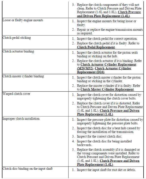
CLUTCH DOES NOT DISENGAGE
Clutch Does Not Disengage
.jpg)
.jpg)
CLUTCH SLIPPING
Clutch Slipping
.jpg)
.jpg)
CLUTCH GRABBING
Clutch Grabbing
.jpg)
.jpg)
CLUTCH RATTLE
Clutch Rattle
.jpg)
.jpg)
RELEASE BEARING NOISY WITH CLUTCH ENGAGED
Release Bearing Noisy with Clutch Engaged
.jpg)
CLUTCH NOISY
Clutch Noisy
.jpg)
CLUTCH PEDAL HARD TO PUSH
Clutch Pedal Hard to Push
.jpg)
.jpg)
READ NEXT:
 Repair instructions
CLUTCH PEDAL REPLACEMENT
NOTE: The clutch pedal is part of the brake, accelerator, and
clutch pedal assembly
and cannot be serviced separately.
To replace the brake, accelerator and clutch pedal asse
Description and operation
CLUTCH SYSTEM DESCRIPTION AND OPERATION
Clutch Spin Down Time
Inspect the clutch spin down time as follows:
Apply the parking brake and block the vehicle wheels.
Shift the manual transmission into
SEE MORE:
Wipers and washers - Repair instructions
WINDSHIELD WIPER AND WASHER SWITCH REPLACEMENT (ENCORE)
Fig. 8: Windshield Wiper And Washer Switch
Windshield Wiper and Washer Switch Replacement (Encore)
WINDSHIELD WIPER AND WASHER SWITCH REPLACEMENT (Encore)
Fig. 9: Windshield Wiper And Washer Switch
Windshield Wiper and Washer Switch Repla
Schematic wiring diagrams
SHIFT LOCK CONTROL WIRING SCHEMATICS (ENCORE)
Shift Lock Control System
Fig. 1: Shift Lock Control System
SHIFT LOCK CONTROL WIRING SCHEMATICS (Encore)
Shift Lock Control System
Fig. 2: Shift Lock Control System
DIAGNOSTIC INFORMATION AND PROCEDURES
DIAGNOSTIC CODE INDEX
DIAGNOSTIC CODE INDEX
© 2020-2026 Copyright www.bencore2.com
