Buick Encore: Horns - Description and operation
HORNS SYSTEM DESCRIPTION AND OPERATION
System Description
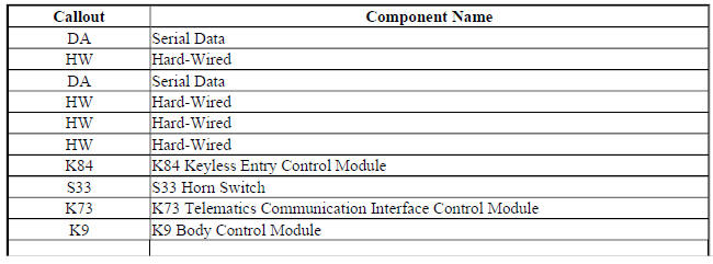
The horn system consists of the following components:
- HORN fuse
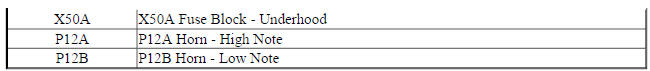
- Underhood fuse block (contains PCB horn relay)
- Horn switch
- Horn-low note
- Horn-high note
- Body control module (BCM)
14 Horns Block Diagram
Fig. 6: 14 Horns Block Diagram
System Operation
The vehicle horn system is activated under the following conditions:
- When the horn switch is depressed
- The BCM commands the horns ON under any of the following conditions:
- When the content theft deterrent system detects a vehicle intrusion-For further information refer to Theft Systems Description and Operation .
- When the panic button is depressed on the remote control door lock transmitter-For further information refer to Keyless Entry System Description and Operation .
- When the keyless entry system is used to lock the vehicle, a horn chirp may sound to notify the driver that the vehicle has been locked. The notification feature may be enabled or disabled through personalization. For further information refer to Keyless Entry System Description and Operation .
- When the OnStar system is used to sound the horns if equipped-For further information, refer to OnStar Description and Operation
Circuit Operation
Battery positive voltage is applied at all times to the horn relay coil and the horn relay switch. Pressing either of the horn switches applies ground to the horn relay control circuit. The BCM may also apply ground to the horn relay control circuit as described above. When the horn relay control circuit is grounded, the horn relay is energized and battery positive voltage is applied to the horns through the horn control circuit. The horns sound as long as ground is applied to the horn relay control circuit.
READ NEXT:
 Immobilizer
Schematic wiring diagrams
IMMOBILIZER WIRING SCHEMATICS (ENCORE)
Immobilzer System
Fig. 1: Immobilzer System
IMMOBILIZER WIRING SCHEMATICS (Encore)
Immobilzer System
Fig. 2: Immobilzer System
Immobilizer - Diagnostic information and procedures
DTC B2955: Security sensor data circuit
DIAGNOSTIC CODE INDEX
DTC B2955: SECURITY SENSOR DATA CIRCUIT
Diagnostic Instructions
Perform the Diagnostic System Check - Vehicle prior to using this
Immobilizer - Repair instructions
THEFT DETERRENT MODULE REPLACEMENT (ENCORE)
Fig. 3: Theft Deterrent Module (Encore)
Theft Deterrent Module Replacement (Encore)
THEFT DETERRENT MODULE REPLACEMENT (Encore)
Fig. 4: Theft Deterren
SEE MORE:
Parasitic Load Explanation & Test Procedures
NOTE: This is GENERAL information. This article is not intended to
be specific to any
unique situation or individual vehicle configuration. For model-specific
information see appropriate articles where available.
GENERAL INFORMATION
NOTE: This is GENERAL information. This article is not intended to
Object Detection and Pedestrian Protection - Repair instructions
Rear object alarm control module replacement
Fig. 8: Rear Object Alarm Control Module
Rear Object Alarm Control Module Replacement
FRONT OBJECT ALARM SENSOR HOUSING REPLACEMENT
Remove the front fascia. Refer to Front Bumper Fascia Replacement (Encore)
, Front Bumper Fascia
Replacement (En
