Buick Encore: Description and operation
DRUM BRAKE SYSTEM DESCRIPTION AND OPERATION
System Component Description
The drum brake system consists of the following:
Drum Brake Shoes
Applies mechanical output force, from hydraulic brake wheel cylinders, to friction surfaces of brake drums.
Brake Drums
Uses mechanical output force applied to friction surface from drum brake shoes to slow speed of tire and wheel assembly rotation.
Brake Drum Hardware
Secures drum brake shoes firmly in proper relationship to hydraulic brake wheel cylinders. Enables sliding motion of brake shoes needed to expand toward friction surface of drums when mechanical output force is applied. Provides return of brake shoes when mechanical output force is relieved.
Brake Drum Adjusting Hardware
Provides automatic adjustments of brake shoes to brake drum friction surface whenever brake apply occurs.
System Operation
Mechanical output force is applied from the hydraulic brake wheel cylinder pistons to the top of the drum brake shoes. The output force is then distributed between the primary and secondary brake shoes as the shoes expand toward the friction surface of the brake drums. The brake shoes apply the output force to the friction surface of the brake drums, which slows the rotation of the tire and wheel assemblies. The proper friction of both the drum brake hardware and adjusting hardware is essential to the proper distribution of braking force.
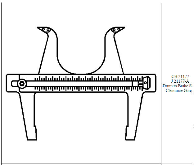
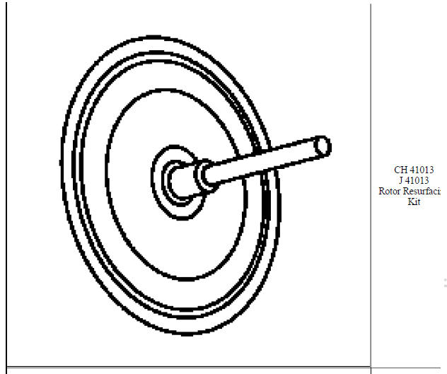
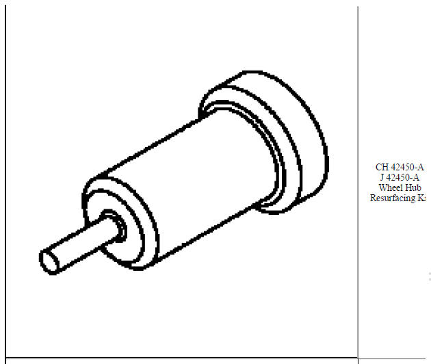
SPECIAL TOOLS AND EQUIPMENT
SPECIAL TOOLS
READ NEXT:
 Diagnostic information and procedures
SPECIFICATIONS
FASTENER TIGHTENING SPECIFICATIONS
Fastener Tightening Specifications
BRAKE COMPONENT SPECIFICATIONS
Brake Component Specifications
BRAKE SYSTEM SPECIFICATIONS
Brake System Specific
Repair instructions
Master cylinder reservoir filling
WARNING: Refer to Brake Fluid Irritant Warning
CAUTION: Refer to Brake Fluid Effects on Paint and Electrical
Components Caution .
Visually inspect the brake fluid
SEE MORE:
Fixed and Moveable Windows - Description and operation
Full-cut method description
NOTE:
If corrosion of the pinch-weld flange is present, or if sheet metal
repairs or
replacements are required, refinish the pinch-weld flange in order to
present a clean, primer-only surface.
If paint repairs are required, mask the flange bonding area, prior to
a
Engine oil and oil filter replacement
Removal Procedure
Open hood.
Place a drain pan below the vehicle.
CAUTION: To prevent damage to oil filter cap ensure proper tool is
used. Do not
use an open end wrench which may cause damage to filter cap.
Using a 24mm socket or closed end wrench loosen oil filter cap. Unscrew
filter cap 3
