Buick Encore: Object Detection and Pedestrian Protection - Diagnostic information and procedures
DTC B094C: Right side object detection control module
DIAGNOSTIC CODE INDEX
.jpg)
.jpg)
Diagnostic Instructions
- Perform the Diagnostic System Check - Vehicle prior to using this diagnostic procedure.
- Review Strategy Based Diagnosis for an overview of the diagnostic approach.
- Diagnostic Procedure Instructions provides an overview of each diagnostic category.
DTC Descriptor
DTC B094C
Right Side Object Detection Control Module
For symptom byte information, refer to Symptom Byte List .
Circuit/System Description
B218R Side Object Sensor Module - Right communicates on a private communication data bus with the B218L Side Object Sensor Module - Left. The B218L Side Object Sensor Module - Left is the master and can set this code if the B218R Side Object Sensor Module - Right determines it has an internal fault. DTC U18A6 will set if the left module is unable to communicate with the right side module.
Conditions for Running the DTC
Ignition ON.
Conditions for Setting the DTC
The B218R Side Object Sensor Module - Right has detected an internal malfunction.
Action Taken When the DTC Sets
- The side object sensor system is disabled..
- The DIC will display "Service Side Detection System".
Conditions for Clearing the DTC
- A current DTC clears when the malfunction is no longer present.
- A history DTC clears when the control module ignition cycle counter reaches the reset threshold of 40, without a repeat of the malfunction.
Diagnostic Aids
- The modules are not identical and cannot be swapped from side to side.
- This DTC may be stored as a history DTC without affecting the operation of the B218R Side Object Sensor Module - Right.
- Do not replace B218R Side Object Sensor Module - Right based only on DTC B094C being set in history.
- If DTC B094C is set as current, replace the B218R Side Object Sensor Module - Right.
- B218R Side Object Sensor Module - Right communicates on a private communication data bus with the B218L Side Object Sensor Module - Left. If programming is needed for module replacement, you must program B218L Side Object Sensor Module - Left which will then in turn program B218R Side Object Sensor Module - Right.
Reference Information
Schematic Reference
Object Detection Schematics (Encore), Object Detection Schematics (Encore)
Connector End View Reference
WIRING SYSTEMS AND POWER MANAGEMENT - COMPONENT CONNECTOR END VIEWS - INDEX - ENCORE WIRING SYSTEMS AND POWER MANAGEMENT - COMPONENT CONNECTOR END VIEWS - INDEX - Encore
Description and Operation
Object Detection Description and Operation (Rearvision Camera, UVC), Object Detection Description and Operation (Rear Park Assist, UD7), Object Detection Description and Operation (Side Blind Zone Alert, UFT), Object Detection Description and Operation (Rear Cross Traffic Alert, UFG)
Electrical Information Reference
- Circuit Testing
- Connector Repairs
- Testing for Intermittent Conditions and Poor Connections
- Wiring Repairs
Scan Tool Reference
Control Module References for scan tool information
Circuit/System Verification
- Ignition ON.
- Verify that B094C is not set.
- If DTC is set
Replace the B218R Side Object Sensor Module - Right.
- If the DTC is not set
- All OK.
Repair Instructions
Perform the Diagnostic Repair Verification after completing the repair.
Control Module References for side object sensor module replacement, programming and setup.
DTC B0954, B0955, B0956, OR B0957: Parking assist front sensor
Diagnostic Instructions
- Perform the Diagnostic System Check - Vehicle prior to using this diagnostic procedure.
- Review Strategy Based Diagnosis for an overview of the diagnostic approach.
- Diagnostic Procedure Instructions provides an overview of each diagnostic category.
DTC Descriptors
DTC B0954
Parking Assist Front Sensor Left Corner Circuit
DTC B0955
Parking Assist Front Sensor Left Middle Circuit
DTC B0956
Parking Assist Front Sensor Right Middle Circuit
DTC B0957
Parking Assist Front Sensor Right Corner Circuit
For symptom byte information, refer to Symptom Byte List .
Diagnostic Fault Information
.jpg)
.gif)
Circuit/System Description
The object sensors are 3-wire sensors that are used to determine the distance between the vehicle and an object of interest. The front and rear parking assist control module supplies 8 V to the object sensors via the 8 V reference circuit and provides ground via the low reference circuit. The front and rear parking assist control module triggers the sensors in a sequential loop. After each sensor transmits, the front and rear parking assist control module uses the sensor echo received through the signal circuit to calculate the distance and position of an object.
Conditions for Running the DTC
Ignition ON
The park assist is activated. The activation takes place through putting in the reverse gear or through operating the park assist switch.
Conditions for Setting the DTC
B0954 01, B0955 01, B0956 01, or B0957 01
The front and rear parking assist control module has detected the voltage at the sensor circuit is greater than 11.5 V or the object sensor is not grounded.
B0954 06, B0955 06, B0956 06, or B0957 06
The front and rear parking assist control module has detected the voltage at the sensor circuit is less than 0.5 V.
B0954 08, B0955 08, B0956 08, or B0957 08
The front and rear parking assist control module has received an invalid signal.
B0954 21, B0955 21, B0956 21, or B0957 21
The object sensor determines no change in the position of an object while the vehicle is in motion
B0954 3A, B0955 3A, B0956 3A, or B0957 3A
The front and rear parking assist control module determines the wrong sensor type is installed.
Action Taken When the DTC Sets
- The parking assist is disabled.
- The driver information center displays SERVICE PARK ASSIST.
Conditions for Clearing the DTC
The condition for setting the DTC is no longer present.
Reference Information
Schematic Reference
Object Detection Schematics (Encore), Object Detection Schematics (Encore)
Connector End View Reference
WIRING SYSTEMS AND POWER MANAGEMENT - COMPONENT CONNECTOR END VIEWS - INDEX - ENCORE WIRING SYSTEMS AND POWER MANAGEMENT - COMPONENT CONNECTOR END VIEWS - INDEX - Encore
Description and Operation
Object Detection Description and Operation (Rearvision Camera, UVC), Object Detection Description and Operation (Rear Park Assist, UD7), Object Detection Description and Operation (Side Blind Zone Alert, UFT), Object Detection Description and Operation (Rear Cross Traffic Alert, UFG)
Electrical Information Reference
- Circuit Testing
- Connector Repairs
- Testing for Intermittent Conditions and Poor Connections Wiring Repairs
Scan Tool Reference
Control Module References for scan tool information
Circuit/System Verification
- Ignition ON.
- Verify that DTC B1405 is not set.
- If the DTC is set
Refer to DTC B1405 (Rear Park Assist - UD7), DTC B1405 (Front and Rear Park Assist - UD5)
- If the DTC is not set
- Verify that DTC B0954 01, B0955 01, B0956 01, B0957 01 B0954 21, B0955 21, B0956 21 or B0957 21 is not set.
- If the DTC is set
- Verify the appropriate B78 Front Object Sensor is free of contamination from snow, mud, dirt, slush or ice.
- If contaminated, clean sensor.
- If there is no contamination
- Refer to Circuit/System Testing.
- If the DTC is not set
- Verify that DTC B0954 3A, B0955 3A, B0956 3A or B0957 3A is not set.
- If the DTC is set
Replace the B78 Front Object Sensor with the correct sensor type.
- If the DTC is not set
- Ignition ON, transmission in REVERSE.
- Verify the scan tool Parking Assist System Status parameter displays Enabled.
- If the Parking Assist System displays Disabled
Refer to Circuit/System Testing.
- If the Parking Assist System displays Enabled
- All OK
Circuit/System Testing
- Ignition OFF, scan tool disconnected, disconnect the harness at the
appropriate B78 Front Object Sensor.
It may take up to 2 min for all vehicle systems to power down.
- Test for less than 10 ohms between the low reference circuit terminal 2 and ground.
- If 10 ohms or greater
- Ignition OFF, disconnect the harness connector X3 at the K41 Front and Rear Parking Assist Control Module.
- Test for less than 2 ohms in the low reference circuit end to end.
- If 2 ohms or greater, repair the open/high resistance in the circuit.
- If less than 2 ohms replace the K41 Front and Rear Parking Assist Control Module.
- If less than 10 ohms
- Ignition ON.
- Test for 7.5-9.5 V between the 8 V reference circuit terminal 1 and ground.
- If less than 7.5 V
- Ignition OFF, disconnect the harness connector at the K41 Front and Rear Parking Assist Control Module.
- Test for infinite resistance between the 8 V reference circuit and ground.
- If less than infinite resistance, repair the short to ground on the
circuit.
If infinite resistance
- Test for less than 2 ohms in the 8 V reference circuit end to end.
- If 2 ohms or greater, repair the open/high resistance in the circuit.
- If less than 2 ohms, replace the K41 Front and Rear Parking Assist Control Module.
- If greater than 9.5 V
- Ignition OFF, disconnect the harness connector at the K41 Front and Rear Parking Assist Control Module, ignition ON.
- Test for less than 1 V between the 8 V reference circuit and ground.
- If 1 V or greater, repair the short to voltage on the circuit.
- If less than 1 V, replace the K41 Front and Rear Parking Assist Control Module.
- If between 7.5-9.5 V
- Ignition OFF, remove the appropriate B78 Front Object Sensor and switch locations with another properly operating sensor. Connect harness connector at both sensors. Ignition ON.
- Verify the DTC is set for the new location in which the malfunctioning sensor is installed.
- If DTC set for the new location
Replace the malfunctioning B78 Front Object Sensor.
- If DTC set for the original location
- Ignition OFF, disconnect the harness connector at the K41 Front and Rear Parking Assist Control Module, ignition ON.
- Test for less than 1 V between the signal circuit and ground.
- If 1 V or greater, repair the short to voltage on the circuit.
- If less than 1 V
- Ignition OFF.
- Test for infinite resistance between the signal circuit and ground.
- If less than infinite resistance, repair the short to ground on the circuit.
- If infinite resistance
- Test for less than 2 ohms in the circuit end to end.
- If 2 ohms or greater, repair the open/high resistance in the circuit.
- If less than 2 ohms, replace the K41 Front and Rear Parking Assist Control Module.
- If no DTC set
- All OK.
Repair Instructions
Perform the Diagnostic Repair Verification after completing the repair.
- Front Object Alarm Sensor Housing Replacement
- Rear Parking Assist Alarm Sensor Replacement
- Control Module References for front and rear parking assist control module replacement, programming and setup.
DTC B0958, B0959, B0960, OR B0961: Parking assist rear sensor
Diagnostic Instructions
- Perform the Diagnostic System Check - Vehicle prior to using this diagnostic procedure.
- Review Strategy Based Diagnosis for an overview of the diagnostic approach.
- Diagnostic Procedure Instructions provides an overview of each diagnostic category.
DTC Descriptors
DTC B0958
Parking Assist Rear Sensor Left Corner Circuit
DTC B0959
Parking Assist Rear Sensor Left Middle Circuit
DTC B0960
Parking Assist Rear Sensor Right Middle Circuit
DTC B0961
Parking Assist Rear Sensor Right Corner Circuit
For symptom byte information, refer to Symptom Byte List .
Diagnostic Fault Information
.jpg)
Circuit/System Description
The object sensors are 3-wire sensors that are used to determine the distance between the vehicle and an object of interest. The front and rear parking assist control module supplies 8 V to the object sensors via the 8 V reference circuit and provides ground via the low reference circuit. The front and rear parking assist control module triggers the sensors in a sequential loop. After each sensor transmits, the front and rear parking assist control module uses the sensor echo received through the signal circuit to calculate the distance and position of an object.
Conditions for Running the DTC
- Ignition ON
- The parking assist is activated. The activation takes place through putting in the reverse gear or through operating the park assist switch.
Conditions for Setting the DTC
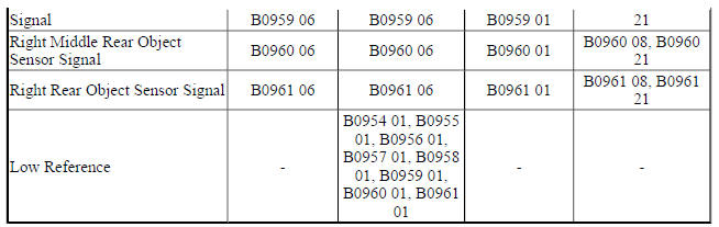
B0958 01, B0959 01, B0960 01, or B0961 01
The front and rear parking assist control module has detected the voltage at the sensor circuit is greater than 11.5 V or the object sensor is not grounded.
B0958 06, B0959 06, B0960 06, or B0961 06
The front and rear parking assist control module has detected the voltage at the sensor circuit less than 0.5 V.
B0958 08, B0959 08, B0960 08, or B0961 08
The front and rear parking assist control module has received an invalid signal.
B0958 21, B0959 21, B0960 21, or B0961 21
The object sensor determines no change in the position of an object while the vehicle is in motion.
B0958 3A, B0959 3A, B0960 3A, or B0961 3A
The front and rear parking assist control module determines the wrong sensor type is installed.
Action Taken When the DTC Sets
- The parking assist is disabled.
- The driver information center displays SERVICE PARK ASSIST.
Conditions for Clearing the DTC
The condition for setting the DTC is no longer present.
Reference Information
Schematic Reference
Object Detection Schematics (Encore), Object Detection Schematics (Encore)
Connector End View Reference
WIRING SYSTEMS AND POWER MANAGEMENT - COMPONENT CONNECTOR END VIEWS - INDEX - ENCORE WIRING SYSTEMS AND POWER MANAGEMENT - COMPONENT CONNECTOR END VIEWS - INDEX - Encore
Description and Operation
Object Detection Description and Operation (Rearvision Camera, UVC), Object Detection Description and Operation (Rear Park Assist, UD7), Object Detection Description and Operation (Side Blind Zone Alert, UFT), Object Detection Description and Operation (Rear Cross Traffic Alert, UFG)
Electrical Information Reference
- Circuit Testing
- Connector Repairs
- Testing for Intermittent Conditions and Poor Connections
- Wiring Repairs
Scan Tool Reference
Control Module References for scan tool information
Circuit/System Verification
- Ignition ON.
- Verify that DTC B1405 is not set.
- If the DTC is set
Refer to DTC B1405 (Rear Park Assist - UD7), DTC B1405 (Front and Rear Park Assist - UD5)
- If the DTC is not set
- Verify that DTC B0958 01, B0959 01, B0960 01, B0961 01, B0958 21, B0959 21, B0960 21 or B0961 21 is not set.
- If the DTC is set
- Verify the B78 Rear Object Sensors are not contaminated with snow, mud, dirt, slush, or ice.
- If contaminated, clean sensor.
- If there is no contamination
- Refer to Circuit/System Testing.
- If the DTC is not set
- Verify that DTC B0958 3A, B0959 3A, B0960 3A or B0961 3A is not set.
- If the DTC is set
Replace the B78 Rear Object Sensor with the correct sensor type.
- If the DTC is not set
- Ignition ON, transmission in REVERSE.
- Verify the scan tool Parking Assist System Status parameter displays Enabled.
- If the Parking Assist System displays Disabled
Refer to Circuit/System Testing.
- If the Parking Assist System displays Enabled
- All OK.
Circuit/System Testing
- Ignition OFF, scan tool disconnected, disconnect the harness at the
appropriate B78 Rear Object Sensor.
It may take up to 2 min for all vehicle systems to power down.
- Test for less than 10 ohms between the low reference circuit terminal 2 and ground.
- If 10 ohms or greater
- Ignition OFF, disconnect the harness connector X2 at the K41 Front and Rear Parking Assist Control Module.
- Test for less than 2 ohms in the low reference circuit end to end.
- If 2 ohms or greater, repair the open/high resistance in the circuit.
- If less than 2 ohms replace the K41 Front and Rear Parking Assist Control Module.
- If less than 10 ohms
- Ignition ON.
- Test for 7.5-9.5 V between the 8 V reference circuit terminal 1 and ground.
- If less than 7.5 V
- Ignition OFF, disconnect the harness connector at the K41 Front and Rear Parking Assist Control Module.
- Test for infinite resistance between the 8 V reference circuit and ground.
- If less than infinite resistance, repair the short to ground on the circuit.
- If infinite resistance
- Test for less than 2 ohms in the 8 V reference circuit end to end.
- If 2 ohms or greater, repair the open/high resistance in the circuit.
- If less than 2 ohms, replace the K41 Front and Rear Parking Assist Control Module.
- If greater than 9.5 V
- Ignition OFF, disconnect the harness connector at the K41 Front and Rear Parking Assist Control Module, ignition ON.
- Test for less than 1 V between the 8 V reference circuit and ground.
- If 1 V or greater, repair the short to voltage on the circuit.
- If less than 1 V, replace the K41 Front and Rear Parking Assist Control Module.
- If between 7.5-9.5 V
- Ignition OFF, remove the appropriate B78 Rear Object Sensor and switch locations with another properly operating sensor. Connect harness connector at both sensors. Ignition ON.
- Verify the DTC is set for the new location in which the malfunctioning sensor is installed.
- If DTC set for the new location
Replace the malfunctioning B78 Rear Object Sensor.
- If DTC set for the original location
- Ignition OFF, disconnect the harness connector at the K41 Front and Rear Parking Assist Control Module, ignition ON.
- Test for less than 1 V between the signal circuit and ground.
- If 1 V or greater, repair the short to voltage on the circuit.
- If less than 1 V
- Ignition OFF.
- Test for infinite resistance between the signal circuit and ground.
- If less than infinite resistance, repair the short to ground on the circuit.
- If infinite resistance
- Test for less than 2 ohms in the circuit end to end.
- If 2 ohms or greater, repair the open/high resistance in the circuit.
- If less than 2 ohms, replace the K41 Front and Rear Parking Assist Control Module.
- If no DTC set
- All OK.
Repair Instructions
Perform the Diagnostic Repair Verification after completing the repair.
- Rear Parking Assist Alarm Sensor Replacement
- Control Module References for front and rear parking assist control module replacement, programming and setup.
DTC B0987: Vehicle direction camera indicator
Diagnostic Instructions
- Perform the Diagnostic System Check - Vehicle prior to using this diagnostic procedure.
- Review Strategy Based Diagnosis for an overview of the diagnostic approach.
- Diagnostic Procedure Instructions provides an overview of each diagnostic category.
DTC Descriptors
DTC B0987 01
Vehicle Direction Camera Indicator Circuit Short to Battery
DTC B0987 06
Vehicle Direction Camera Indicator Circuit Low Voltage/Open
DTC B0987 0B
Vehicle Direction Camera Indicator Circuit High Current
Diagnostic Fault Information
.jpg)
Circuit/System Description
The lane departure warning is enabled and disabled through the lane departure warning switch located in the center console. When enabled, the frontview camera module will illuminate the indicator located in the switch.
The BCM supplies voltage to the indicator from the lighting dimming circuit. The frontview camera module turns on the indicator by proving the ground.
Conditions for Running the DTC
Ignition ON.
Conditions for Setting the DTC
B0987 01
The frontview camera module detects a short to voltage in the control circuit.
B0987 06
The frontview camera module detects a short to ground or an open/high resistance in the control circuit.
B0987 0B
The active safety control module detects high current in the control circuit.
Action Taken When the DTC Sets
- Lane departure warning is disabled
- The driver information center displays "Service Front Camera".
Conditions for Clearing the DTC
The condition for setting the DTC is no longer present.
Reference Information
Schematic Reference
Object Detection Schematics (Encore), Object Detection Schematics (Encore)
Connector End View Reference
WIRING SYSTEMS AND POWER MANAGEMENT - COMPONENT CONNECTOR END VIEWS - INDEX - ENCORE WIRING SYSTEMS AND POWER MANAGEMENT - COMPONENT CONNECTOR END VIEWS - INDEX - Encore
Description and Operation
Object Detection Description and Operation (Rearvision Camera, UVC), Object Detection Description and Operation (Rear Park Assist, UD7), Object Detection Description and Operation (Side Blind Zone Alert, UFT), Object Detection Description and Operation (Rear Cross Traffic Alert, UFG)
Electrical Information Reference
- Circuit Testing
- Connector Repairs
- Testing for Intermittent Conditions and Poor Connections
- Wiring Repairs
Scan Tool Reference
Control Module References for scan tool information
Circuit/System Verification
- Ignition ON.
- Verify DTC B356A is not set.
- If the DTC is set
Refer to DTC B356A
- If the DTC is not set
- Verify the lane departure warning indicator turns ON and OFF when pressing and releasing the lane departure warning switch.
- If the indicator does not turn ON and OFF
Refer to Circuit/System Testing.
- If the indictor turns ON and OFF
- All OK.
Circuit/System Testing
- Ignition OFF, and all vehicle systems OFF, disconnect the harness connector at the S48E Multifunction Switch - Center Console, ignition ON.
- Test for 9.1 - 12.6 V between the dimming control circuit terminal 8 and ground.
NOTE: Verify interior lighting dimming is turned all the way up.
- If less than 9.1 V
- Ignition OFF, disconnect the X1 harness connector at the K9 Body Control Module.
- Test for infinite resistance between the control circuit and ground.
- If less than infinite resistance, repair the short to ground on the circuit.
- If infinite resistance
- Test for less than 2 ohms in the control circuit end to end.
- If 2 ohms or greater, repair the open/high resistance in the circuit.
- If less than 2 ohms, refer to Interior Backlighting Malfunction .
- If greater than 12.6 V
- Ignition OFF, disconnect the X1 harness connector at the K9 Body Control Module, ignition ON.
- Test for less than 1 V between the control circuit and ground.
- If 1 V or greater, repair the short to voltage on the circuit.
- If less than 1 V, refer to Interior Backlighting Malfunction .
- If between 9.1- 12.6 V
- Ignition OFF, disconnect the harness connector at the K109 Frontview Camera Module, ignition ON.
- Test for less than 1 V between the control circuit terminal 6 and ground.
- If 1 V or greater
Repair the short to voltage on the circuit.
- If less than 1 V
- Ignition OFF.
- Test for infinite resistance between the control circuit terminal 6 and ground.
- If less than infinite resistance
Repair the short to ground on the circuit.
- If infinite resistance
- Test for less than 5 ohms between the K109 Frontview Camera Module terminal 4 and S48E Multifunction Switch - Center Console circuit terminal 6.
- If greater than 5 ohms
Repair the open/high resistance in the circuit.
- If less than 5 ohms
- Test or replace the S48E Multifunction Switch - Center Console.
- Verify the lane departure switch Indicator turns ON and OFF when pressing and releasing the lane departure warning switch.
- If indicator does not turn on and off
Replace K109 Frontview Camera Module.
- If indicator turns on and off
- All OK.
Repair Instructions
Perform the Diagnostic Repair Verification after completing the repair
- Accessory Switch Replacement (Encore) , Accessory Switch Replacement (Encore)
- Control Module References for frontview camera module replacement, programming and setup.
DTC B1011: System disabled information stored malfunction
Diagnostic Instructions
- Perform the Diagnostic System Check - Vehicle prior to using this diagnostic procedure.
- Review Strategy Based Diagnosis for an overview of the diagnostic approach.
- Diagnostic Procedure Instructions provides an overview of each diagnostic category.
DTC Descriptor
DTC B1011 00
System Disabled Information Stored Malfunction
Circuit/System Description
The frontview camera module permanently monitors the serial data bus for error messages. When a malfunction is detected by the frontview camera module, the system will be disabled and an error message will be stored in the frontview camera module disable history buffer which is used to store information about the front camera features that are disabled.
Conditions for Running the DTC
- Ignition ON
- Frontview camera enabled
Conditions for Setting the DTC
The frontview camera module detects a malfunction.
Action Taken When the DTC Sets
- The frontview camera module is disabled.
- The frontview camera module disable history buffer stores information why the system was disabled.
Conditions for Clearing the DTC
The condition for setting the DTC is no longer present.
Diagnostic Aids
The frontview camera module disable history buffers are used to store information about the frontview camera module features that are disabled. The buffers will only update if the disable condition changes.
Example: If the data received from the steering wheel angle sensor is Invalid across many ignition cycles then it will only appear in 1 history buffer and not all history buffers. If this condition is the current reason why the frontview camera module is disabled then it will be set in frontview camera module disable history buffer 1. If a new reason occurs, such as vehicle speed validity is invalid, then the invalid steering wheel angle sensor fault will shift into disable history buffer 2 and vehicle speed validity invalid will be in disable history buffer 1. Since there are only 4 disable history buffers, the invalid steering wheel angle sensor will age out if 4 other disable reasons occur since the last invalid steering wheel angle sensor event occurred. Frontview camera module disable history buffer 1 contains the current reason that one of the frontview camera module features is disabled.
The frontview camera module disable history buffers can display the following values:
- Lane Departure Warning Indicator Malfunction
- Lane Departure Warning Switch Malfunction
- Camera Obstructed
- Accelerator Pedal Position Out of Range
- Driven Wheel Speed Signal Invalid
- Non-Driven Wheel Speed Signal Invalid
- Brake Pedal Moderate Travel Signal Invalid
- Brake Pedal Initial Travel Position Achieved
- Lost Communication with Steering Wheel Angle Sensor Module
- Invalid Data Received From Steering Wheel Angle Sensor Module
- Forward Collision Alert Switch Malfunction
- Clutch Pedal Position (CPP) Sensor Performance
- Clutch Pedal Position (CPP) Sensor Performance
- Transmission Gear Engaged
- Acceleration Sensor Longitudinal Signal
- Invalid Data Received From Yaw Rate Sensor Module
- Power Mode Controlled by Backup Device
- System Power Mode
- Overvoltage
- Undervoltage
- Undefined
Reference Information
Schematic Reference
Object Detection Schematics (Encore), Object Detection Schematics (Encore)
Connector End View Reference
WIRING SYSTEMS AND POWER MANAGEMENT - COMPONENT CONNECTOR END VIEWS - INDEX - ENCORE WIRING SYSTEMS AND POWER MANAGEMENT - COMPONENT CONNECTOR END VIEWS - INDEX - Encore
Description and Operation
Object Detection Description and Operation (Rearvision Camera, UVC), Object Detection Description and Operation (Rear Park Assist, UD7), Object Detection Description and Operation (Side Blind Zone Alert, UFT), Object Detection Description and Operation (Rear Cross Traffic Alert, UFG)
Electrical Information Reference
- Circuit Testing
- Connector Repairs
- Testing for Intermittent Conditions and Poor Connections
- Wiring Repairs
Scan Tool Reference
Control Module References for scan tool information
Circuit/System Verification
NOTE: Do not replace K109 Frontview Camera Module for this DTC. DTC B1011 is an information DTC.
- gnition ON.
- Verify no other DTC is set except for DTC B1011.
- If any other DTCs are set
Diagnose those first. Refer to Diagnostic Trouble Code (DTC) List - Vehicle .
- If no other DTCs are set
NOTE: When referring to Frontview Camera Disable History, some items such as Non-Driven Wheel Speed Signal Invalid and Driven Wheel Speed Signal Invalid may routinely be stored without B1011 being set. If B1011 has not set, disregard any information stored in the buffers as it is not indicative of a problem.
- Refer to Diagnostic Aids and Frontview Camera Disable History for what caused B1011 to set. Diagnose the system that set the malfunction
Repair Instructions
Perform the Diagnostic Repair Verification after completing the repair.
Control Module References for frontview camera module programming and setup
DTC B1015: Vehicle identification number information malfunction
Diagnostic Instructions
- Perform the Diagnostic System Check - Vehicle prior to using this diagnostic procedure.
- Review Strategy Based Diagnosis for an overview of the diagnostic approach.
- Diagnostic Procedure Instructions provides an overview of each diagnostic category.
DTC Descriptor
DTC B1015 00
Vehicle Identification Number Information Malfunction
Circuit/System Description
When the ignition is turned ON, the front and rear parking assist control module and frontview camera module receives the vehicle identification number (VIN) from the body control module. The modules will compare the VIN received to the VIN stored in memory.
Conditions for Running the DTC
Ignition voltage is between 9-16 V.
Conditions for Setting the DTC
The stored VIN does not match the received VIN.
Action Taken When the DTC Sets
- The parking assist system, lane departure warning system, and forward collision alert system is disabled.
- The driver information center displays SERVICE PARK ASSIST or SERVICE LANE DEPARTURE SYSTEM.
Conditions for Clearing the DTC
The stored VIN matches the VIN stored in the body control module.
Reference Information
Schematic Reference
Object Detection Schematics (Encore), Object Detection Schematics (Encore)
Connector End View Reference
WIRING SYSTEMS AND POWER MANAGEMENT - COMPONENT CONNECTOR END VIEWS - INDEX - ENCORE WIRING SYSTEMS AND POWER MANAGEMENT - COMPONENT CONNECTOR END VIEWS - INDEX - Encore
Description and Operation
Object Detection Description and Operation (Rearvision Camera, UVC), Object Detection Description and Operation (Rear Park Assist, UD7), Object Detection Description and Operation (Side Blind Zone Alert, UFT), Object Detection Description and Operation (Rear Cross Traffic Alert, UFG)
Electrical Information Reference
- Circuit Testing
- Connector Repairs
- Testing for Intermittent Conditions and Poor Connections
- Wiring Repairs
Scan Tool Reference
Control Module References for scan tool information
Circuit/System Verification
- Ignition ON.
- Verify DTC B1015 is not.
- If DTC B1015 is set
- Program the control module the DTC originally set in.
- Verify the DTC does not set.
- If the DTC is sets, replace the control module the DTC set in.
- If the DTC does not set
- All OK
- If DTC B1015 is not set
- All OK
Repair Instructions
Perform the Diagnostic Repair Verification after completing the repair
Control Module References for the front and rear parking assist control module and frontview camera module replacement, programming and setup.
DTC B101D (with side blind zone alert, uft): electronic control unit hardware
Diagnostic Instructions
- Perform the Diagnostic System Check - Vehicle prior to using this diagnostic procedure.
- Review Strategy Based Diagnosis for an overview of the diagnostic approach.
- Diagnostic Procedure Instructions provides an overview of each diagnostic category.
DTC Descriptor
DTC B101D
Electronic Control Unit Hardware
For symptom byte information, refer to Symptom Byte List .
Circuit/System Description
The side detection system uses two modules B218L Side Object Sensor Module - Left and B218R Side Object Sensor Module - Right. The left module is the master and is on the vehicle's serial data bus and communicates to the right module on a private bus. The internal fault detection is handled inside the B218L Side Object Sensor Module - Left. No external circuit diagnosis is involved.
Conditions for Setting the DTC
- The B218L Side Object Sensor Module - Left runs the program to detect an internal fault when power up is commanded.
Conditions for Setting the DTC
The B218L Side Object Sensor Module - Left has detected an internal malfunction
Action Taken When the DTC Sets
- The side object sensor system is disabled.
- The driver information center displays SERVICE SIDE DETECTION SYSTEM
Conditions for Clearing the DTC
- A current DTC clears when the malfunction is no longer present.
- A history DTC clears when the device ignition cycle counter reaches the reset threshold of 50, without a repeat of the malfunction.
Diagnostic Aids
- This DTC may be stored as a history DTC without affecting the operation of the B218L Side Object Sensor Module - Left.
- Do not replace B218L Side Object Sensor Module - Left based only on DTC B101D being set in history.
- If DTC B101D is set as current, replace the B218L Side Object Sensor Module - Left.
- Since the left module is the master, if it is replaced, there still may be a problem with the right side as the module may have been unable to report it. Once the left module is replaced, check DTCs and verify operation of the system to assure proper functionality.
Reference Information
Schematic Reference
- Data Communication Schematics (Encore) , Data Communication Schematics (Encore)
- Control Module References
Connector End View Reference
WIRING SYSTEMS AND POWER MANAGEMENT - COMPONENT CONNECTOR END VIEWS - INDEX - ENCORE WIRING SYSTEMS AND POWER MANAGEMENT - COMPONENT CONNECTOR END VIEWS - INDEX - Encore
Description and Operation
Data Link Communications Description and Operation
Electrical Information Reference
- Circuit Testing
- Connector Repairs
- Testing for Intermittent Conditions and Poor Connections
- Wiring Repairs
Scan Tool Reference
Control Module References for scan tool information
Circuit/System Verification
- Ignition ON.
- Verify DTC B101D is not set.
- If DTC B101D is set
- Replace the B218L Side Object Sensor Module - Left.
- Verify no new DTCs set and side object system operates properly
- If there are new DTCs refer to Diagnostic Trouble Code (DTC) List - Vehicle , or if the system does not operate properly, refer to Side Object System Malfunction.
- If there are no new DTCs and the side object system operates properly
- If DTC B101D is not set
- All OK
Repair Instructions
Perform the Diagnostic Repair Verification after completing the repair.
Control Module References for B218L Side Object Sensor Module - Left replacement, programming and setup.
DTC B1405 (Rear park assist - ud7): control module voltage reference output 2
Diagnostic Instructions
- Perform the Diagnostic System Check - Vehicle prior to using this diagnostic procedure.
- Review Strategy Based Diagnosis for an overview of the diagnostic approach.
- Diagnostic Procedure Instructions provides an overview of each diagnostic category.
DTC Descriptors
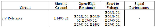
DTC B1405 02
Control Module Voltage Reference Output 2 Circuit Short to Ground
DTC B1405 03
Control Module Voltage Reference Output 2 Circuit Low Voltage
DTC B1405 07
Control Module Voltage Reference Output 2 Circuit High Voltage
Diagnostic Fault Information
.jpg)
Circuit/System Description
The object sensors are 3-wire sensors that are used to determine the distance between the vehicle and an object of interest. The front and rear parking assist control module supplies 8 V to the object sensors via the object sensor supply voltage circuit and provides ground via the object sensor low reference circuit. The front and rear parking assist control module triggers the sensors in a sequential loop. After each sensor transmits, the front and rear parking assist control module uses the sensor echo received through the object sensor signal circuit to calculate the distance and position of an object.
Conditions for Running the DTC
- Ignition ON, engine RUNNING
- Transmission in REVERSE
Conditions for Setting the DTC
B1405 02
The rear parking assist control module has detected the object sensor supply voltage circuit is shorted to ground.
B1405 03
The rear parking assist control module has detected the object sensor supply voltage circuit is less than 7.2 V.
B1405 07
The rear parking assist control module has detected the object sensor supply voltage circuit is greater than 9.2 V.
Action Taken When the DTC Sets
- The parking assist system is disabled.
- The driver information center displays SERVICE PARK ASSIST.
Conditions for Clearing the DTC
The condition for setting the DTC is no longer present.
Reference Information
Schematic Reference
Object Detection Schematics (Encore), Object Detection Schematics (Encore)
Connector End View Reference
WIRING SYSTEMS AND POWER MANAGEMENT - COMPONENT CONNECTOR END VIEWS - INDEX - ENCORE WIRING SYSTEMS AND POWER MANAGEMENT - COMPONENT CONNECTOR END VIEWS - INDEX - Encore
Description and Operation
Object Detection Description and Operation (Rearvision Camera, UVC), Object Detection Description and Operation (Rear Park Assist, UD7), Object Detection Description and Operation (Side Blind Zone Alert, UFT), Object Detection Description and Operation (Rear Cross Traffic Alert, UFG)
Electrical Information Reference
- Circuit Testing
- Connector Repairs
- Testing for Intermittent Conditions and Poor Connections
- Wiring Repairs
Scan Tool Reference
Control Module References for scan tool information
Circuit/System Verification
- Ignition ON, engine running, transmission in R.
- Verify the scan tool Park Assist Sensor Reference Voltage parameter is between 7.2-9.2 V.
- If Park Assist Sensor Reference Voltage is not between 7.2-9.2 V
Refer to Circuit/System Testing
- If Park Assist Sensor Reference Voltage is between 7.2-9.2 V
- All OK.
Circuit/System Testing
- Ignition OFF, disconnect the X2 harness connector at the K41R Rear Parking Assist Control Module, ignition ON.
- Test for less than 1 V between the 8 V reference circuit terminal 4 and ground.
- If 1 V or greater
Repair the short to voltage on the circuit.
- If less than 1 V
- Ignition OFF.
- Test for infinite resistance between the 8 V reference circuit terminal 4 and ground.
- If less than infinite resistance
Repair the short to ground on the circuit.
- If infinite resistance
- Replace the K41R Rear Parking Assist Control Module.
Repair Instructions
Perform the Diagnostic Repair Verification after completing the repair.
Control Module References for rear parking assist control module replacement, programming and setup.
DTC B1405 (Front and rear park assist - ud5): control module voltage reference output 2
Diagnostic Instructions
- Perform the Diagnostic System Check - Vehicle prior to using this diagnostic procedure.
- Review Strategy Based Diagnosis for an overview of the diagnostic approach.
- Diagnostic Procedure Instructions provides an overview of each diagnostic category.
DTC Descriptors
DTC B1405 02
Control Module Voltage Reference Output 2 Circuit Short to Ground
DTC B1405 03
Control Module Voltage Reference Output 2 Circuit Low Voltage
DTC B1405 07
Control Module Voltage Reference Output 2 Circuit High Voltage
Diagnostic Fault Information
.jpg)
Circuit/System Description
The object sensors are 3-wire sensors that are used to determine the distance between the vehicle and an object of interest. The front and rear parking assist control module supplies 8 V to the object sensors via the object sensor supply voltage circuit and provides ground via the object sensor low reference circuit. The front and rear parking assist control module triggers the sensors in a sequential loop. After each sensor transmits, the front and rear parking assist control module uses the sensor echo received through the object sensor signal circuit to calculate the distance and position of an object.
Conditions for Running the DTC
- Ignition ON, engine RUNNING
- Transmission in REVERSE
Conditions for Setting the DTC
B1405 02
The front and rear parking assist control module has detected the object sensor supply voltage circuit is shorted to ground.
B1405 03
The front and rear parking assist control module has detected the object sensor supply voltage circuit is less than 7.2 V.
B1405 07
The front and rear parking assist control module has detected the object sensor supply voltage circuit is greater than 9.2 V.
Action Taken When the DTC Sets
- The parking assist is disabled.
- The driver information center displays SERVICE PARK ASSIST.
Conditions for Clearing the DTC
The condition for setting the DTC is no longer present.
Reference Information
Schematic Reference
Object Detection Schematics (Encore), Object Detection Schematics (Encore)
Connector End View Reference
WIRING SYSTEMS AND POWER MANAGEMENT - COMPONENT CONNECTOR END VIEWS - INDEX - ENCORE WIRING SYSTEMS AND POWER MANAGEMENT - COMPONENT CONNECTOR END VIEWS - INDEX - Encore
Description and Operation
Object Detection Description and Operation (Rearvision Camera, UVC), Object Detection Description and Operation (Rear Park Assist, UD7), Object Detection Description and Operation (Side Blind Zone Alert, UFT), Object Detection Description and Operation (Rear Cross Traffic Alert, UFG)
Electrical Information Reference
- Circuit Testing
- Connector Repairs
- Testing for Intermittent Conditions and Poor Connections
- Wiring Repairs
Scan Tool Reference
Control Module References for scan tool information
Circuit/System Verification
Ignition ON, engine running, transmission in R.
Verify the scan tool Park Assist Sensor Reference Voltage parameter is between 7.2-9.2 V.
- If Park Assist Sensor Reference Voltage is not between 7.2-9.2 V
Refer to Circuit/System Testing
- If Park Assist Sensor Reference Voltage is between 7.2-9.2V
- All OK.
Circuit/System Testing
- Ignition OFF, disconnect harness connectors X2 and X3 at the K41 Front and Rear Parking Assist Control Module, ignition ON.
- Test for less than 1 V between the 8 V reference circuit terminals listed below and ground.
- Terminal 4 X2
- Terminal 1 X3
- If 1 V or greater
Repair the short to voltage on the circuit.
- If less than 1 V
- Ignition OFF.
- Test for infinite resistance between 8V reference circuit terminals listed below and ground.
- Terminal 4 X2
- Terminal 1 X3
- If less than infinite resistance
Repair the short to ground on the circuit.
- If infinite resistance
- Replace the K41 Front and Rear Parking Assist Control Module.
Repair Instructions
Perform the Diagnostic Repair Verification after completing the repair.
- Front Object Alarm Sensor Housing Replacement
- Rear Parking Assist Alarm Sensor Replacement
- Control Module References for front and rear parking assist control module replacement, programming and setup.
DTC B356A: Vehicle direction warning switch circuit
Diagnostic Instructions
- Perform the Diagnostic System Check - Vehicle prior to using this diagnostic procedure.
- Review Strategy Based Diagnosis for an overview of the diagnostic approach.
- Diagnostic Procedure Instructions provides an overview of each diagnostic category.
DTC Descriptors
DTC B356A 02
Vehicle Direction Warning Switch Circuit Short to Ground
DTC B356A 05
Vehicle Direction Warning Switch Circuit Short to Voltage
Diagnostic Fault Information
.jpg)
Circuit/System Description
The lane departure warning feature is enabled and disabled through the lane departure switch located in the left steering wheel controls switch. When enabled, the frontview camera module will illuminate the indicator located in the switch. The forward collision alert distance is adjustable using the forward collision switch located in the center console. The setting is shown in the driver information center.
When the system is operating and can detect the lane markings, the frontview camera module will request via serial data communications that the instrument panel cluster illuminate the green lane departure ready-to-assist indicator. If the frontview camera module detects that the vehicle has crossed a lane marking without the turn signal being used, the module will request that the instrument cluster flash the yellow lane departure warning indicator. An audible warning will also sound three times when the yellow instrument cluster indicator is flashing.
Conditions for Running the DTC
Ignition ON.
Conditions for Setting the DTC
DTC B356A 02
The frontview camera module has detected a short to ground for more than 10 s.
DTC B356A 05
The frontview camera module has detected a short to voltage or an open/high resistance for more than 10 s.
Action Taken When the DTC Sets
- Lane departure and forward collision warning features are disabled.
- Service Front Camera is displayed on the driver information center.
Conditions for Clearing the DTC
- The condition responsible for setting the DTC no longer exists.
- A history DTC will clear once 100 consecutive malfunction-free ignition cycles have occurred
Diagnostic Aids
Manually pressing the lane departure warning switch or forward collision alert switch for approximately 10 s will cause this DTC to set.
Reference Information
Schematic Reference
Object Detection Schematics (Encore), Object Detection Schematics (Encore)
Connector End View Reference
WIRING SYSTEMS AND POWER MANAGEMENT - COMPONENT CONNECTOR END VIEWS - INDEX - ENCORE WIRING SYSTEMS AND POWER MANAGEMENT - COMPONENT CONNECTOR END VIEWS - INDEX - Encore
Description and Operation
Object Detection Description and Operation (Rearvision Camera, UVC), Object Detection Description and Operation (Rear Park Assist, UD7), Object Detection Description and Operation (Side Blind Zone Alert, UFT), Object Detection Description and Operation (Rear Cross Traffic Alert, UFG)
Electrical Information Reference
- Circuit Testing
- Connector Repairs
- Testing for Intermittent Conditions and Poor Connections
- Wiring Repairs
Scan Tool Reference
Control Module References for scan tool information
Circuit/System Verification
- Ignition ON.
- Verify the scan tool Lane Departure Warning Switch Status parameter changes between Open and Closed while pressing and releasing the lane departure warning switch.
- If the parameter does not change
Refer to Circuit/System Testing.
- If the parameter changes
- Verify the driver information center displays and adjusts forward collision alert setting while repeatedly pressing and releasing the forward collision switch. The setting should change cycle between far, medium, near, and off.
- If the display does not change
Refer to Circuit/System Testing.
- If the display changes
- All OK.
Circuit/System Testing
- Ignition OFF and all vehicle systems OFF, disconnect the harness connectors at the S48E Multifunction Switch - Center Console and S70L Steering Wheel Controls Switch - Left. It may take up to 2 min for all vehicle systems to power down.
- Test for less than 10 ohms between the following ground circuit terminals and ground:
- S48E Multifunction Switch - Center Console terminal 9
- S70L Steering Wheel Controls Switch - Left terminal 7
- If 10 ohms or greater
- Test for less than 2 ohms in the ground circuit end to end.
- If 2 ohms or greater, repair the open/high resistance in the circuit.
- If less than 2 ohms, repair the open/high resistance in the ground connection.
- If less than 10 ohms
- Ignition ON.
- Verify the scan tool Lane Departure Warning Switch Status parameter is Open.
- If not Open
- Ignition OFF, disconnect the harness connector at the K109 Frontview Camera Module.
- Test for infinite resistance between the S48E Multifunction Switch - Center Console signal circuit terminal 7 and ground.
- If less than infinite resistance, repair the short to ground on the circuit.
- If infinite resistance, replace the K109 Frontview Camera Module.
- If Open
- Install a 3 A fused jumper wire between the S48E Multifunction Switch - Center Console signal circuit terminal 7 and ground.
- Verify DTC B356A 02 sets in approximately 10 s.
- If DTC does not set
- Ignition OFF, remove the jumper wire, disconnect the harness connector at the K109 Frontview Camera Module, ignition ON.
- Test for less than 1 V between the signal circuit and ground.
- If 1 V or greater, repair the short to voltage on the circuit.
- If less than 1 V
- Test for less than 2 ohms in the signal circuit end to end.
- If 2 ohms or greater, repair the open/high resistance in the circuit.
- If less than 2 ohms, replace the K109 Frontview Camera Module.
- If DTC sets
- Test or replace the S48E Multifunction Switch - Center Console or S70L Steering Wheel Controls Switch - Left.
Component Test
Forward Collision Alert Switch
- Ignition OFF, disconnect the harness connector at the S70L Steering Wheel Controls Switch - Left.
- Test for infinite resistance between the control circuit terminal 2 and ground circuit terminal 7.
- If less than infinite resistance
Replace the S70L Steering Wheel Controls Switch - Left.
- If infinite resistance
- Test for 1.0k - 1.5k ohms between the control circuit terminal 2 and ground circuit terminal 7 while pressing forward collision alert switch.
- If not between 1.0k - 1.5k ohms
Replace the S70L Steering Wheel Controls Switch - Left.
- If between 1.0k - 1.5k ohms
- All OK.
Lane Departure Warning Switch
- Ignition OFF, disconnect the harness connector at the S48E Multifunction Switch - Center Console.
- Test for infinite resistance between the control circuit terminal 7 and ground circuit terminal 9.
- If less than infinite resistance
Replace the S48E Multifunction Switch - Center Console.
- If infinite resistance
- Test for 3.8k - 5.8k ohms between the control circuit terminal 7 and ground circuit terminal 9 while pressing the lane departure warning switch.
- If not between 3.8k - 5.8k ohms
Replace the S48E Multifunction Switch - Center Console.
- If between 3.8k - 5.8k ohms
- All OK.
Repair Instructions
Perform the Diagnostic Repair Verification after completing the repair.
- Accessory Switch Replacement (Encore) , Accessory Switch Replacement (Encore)
- Cruise Control Switch Replacement
- Control Module References for frontview camera module replacement, programming, and setup.
SYMPTOMS - OBJECT DETECTION
NOTE: The following steps must be completed before using the symptom tables:
- Perform the Diagnostic System Check - Vehicle before using the Symptom List in order to verify that all of the following are true:
- There are no DTCs set.
- The control modules can communicate via the serial data link.
NOTE: The rear vision camera does not communicate on the serial data bus.
- Review the system operation in order to familiarize yourself with the system functions. Refer to Object Detection Description and Operation (Rearvision Camera, UVC), Object Detection Description and Operation (Rear Park Assist, UD7), Object Detection Description and Operation (Side Blind Zone Alert, UFT), Object Detection Description and Operation (Rear Cross Traffic Alert, UFG).
Visual/Physical Inspection
- Inspect for aftermarket devices which may affect the operation of the system. Refer to Checking Aftermarket Accessories .
- Inspect the easily accessible or visible system components for obvious damage or conditions which may cause the symptom.
- Make sure the parking assist sensors located on the vehicle front and rear bumper are clear. Remove any snow, mud or ice that is blocking the sensors.
Intermittent
Faulty electrical connections or wiring may be the cause of intermittent conditions. Refer to Testing for Intermittent Conditions and Poor Connections .
Symptom List
- Lane Departure Warning System Malfunction
- Parking Assist System Malfunction
- Rear Vision Camera System Malfunction
Front view camera module malfunction (forward collision alert - UEU)
Diagnostic Instructions
- Perform the Diagnostic System Check - Vehicle prior to using this diagnostic procedure.
- Review Strategy Based Diagnosis for an overview of the diagnostic approach.
- Diagnostic Procedure Instructions provides an overview of each diagnostic category.
Diagnostic Fault Information
.jpg)
Circuit/System Description
The forward collision alert system is controlled by the front view camera module mounted on the windshield.
The forward collision alert system is always active and operates at speeds above 40 km/h (25 mph). When the system detects a vehicle in the path ahead, the green vehicle ahead alert indicator in the instrument cluster is illuminated. When approaching another vehicle too rapidly, the collision alert symbol will flash in the instrument cluster and the radio will simultaneously give an audible alert sound. The red collision alert display will stay continuously illuminated if the vehicle ahead remains much too close. These actions are requested by the front view camera module via serial data to the instrument cluster. The forward collision alert switch is part of the left steering wheel controls and is used to adjust the timing sensitivity of the front collision alert system
Diagnostic Aids
Certain factors will affect the operation of the forward collision alert system. Forward collision alert does not warn the driver of any objects that are not detected as a vehicle, like e.g. pedestrians, animals, signs, guard rails, bridges, construction barrels or other stationary or slow moving objects. In some cases the camera may detect a vehicle that is not in the path ahead, or the system may occasionally provide unrealistic alerts. This could respond to a turning vehicle ahead, guard rails, traffic signs, or other stationary objects. This is normal operation, the vehicle does not need service. When the system is operating properly, the green vehicle ahead alert indicator will illuminate on the vehicle direction display when the system detects a vehicle in the path ahead. This indicates that all of the required operating conditions are met. The green vehicle ahead alert indicator will not appear when the system is having difficulty seeing other vehicles on the road or if the view of the front view camera is blocked with mud, dirt, snow, ice, or slush, if the windshield is damaged, or when weather limits visibility, such as while driving in fog, rain, or snow conditions. This is normal operation, the vehicle does not need service.
Additionally, the Front View Camera Disable History can give useful hints about what affected the operation of the lane departure warning system. For the Front View Camera Disable History refer to DTC B1011.
Reference Information
Schematic Reference
Object Detection Schematics (Encore), Object Detection Schematics (Encore)
Connector End View Reference
WIRING SYSTEMS AND POWER MANAGEMENT - COMPONENT CONNECTOR END VIEWS- INDEX - ENCORE WIRING SYSTEMS AND POWER MANAGEMENT - COMPONENT CONNECTOR END VIEWS - INDEX - Encore
Description and Operation
Object Detection Description and Operation (Rearvision Camera, UVC), Object Detection Description and Operation (Rear Park Assist, UD7), Object Detection Description and Operation (Side Blind Zone Alert, UFT), Object Detection Description and Operation (Rear Cross Traffic Alert, UFG)
Electrical Information Reference
- Circuit Testing
- Connector Repairs
- Testing for Intermittent Conditions and Poor Connections
- Wiring Repairs
Scan Tool Reference
Control Module References for scan tool information
Circuit/System Verification
NOTE: Refer to Diagnostic Aids before performing Circuit/System Verification
- Ignition ON.
- Verify the scan tool Forward Collision Alert Function Status parameter is Off, Disabled, Not Ready To Assist or Ready To Assist.
- If the parameter is Malfunction
Refer to Circuit/System Testing - Frontview Camera Module Malfunction
- If the parameter is not Malfunction
- Verify the driver information center displays and adjusts forward collision alert setting while repeatedly pressing and releasing the forward collision switch. The setting should cycle between far, medium, near, and off.
- If the display does not change
Refer to Circuit/System Testing - Forward Collision Alert Switch Malfunction.
- If the display changes
- Verify the K109 Frontview Camera Module has good visibility to the road ahead.
- If visibility is poor
Clean windshield
- If visibility is good
- All OK.
Circuit/System Testing
NOTE: You must perform the Circuit/System Verification before proceeding with Circuit/System Testing.
Frontview Camera Module Malfunction
- Ignition ON.
- Verify no DTCs are set.
- If DTCs are set
Diagnose and repair DTCs. Refer to Diagnostic Trouble Code (DTC) List - Vehicle .
- If no DTCs are set
- Ignition OFF and all vehicle systems OFF. It may take up to 2 min for
all vehicle systems to power down.
Disconnect the harness connector at the K109 Frontview Camera Module.
- Test for less than 10 ohms between the ground circuit terminal 1 and ground.
- If 10 ohms or greater
- Ignition OFF.
- Test for less than 2 ohms in the ground circuit end to end.
- If 2 ohms or greater, repair the open/high resistance in the circuit.
- If less than 2 ohms, repair the open/high resistance in the ground connection.
- If less than 10 ohms
- Verify a test lamp illuminates between the B+ circuit terminal 3 and ground.
- If the test lamp does not illuminate and the circuit fuse is good
- Ignition OFF.
- Test for less than 2 ohms in the B+ circuit end to end.
- If 2 ohms or greater, repair the open/high resistance in the circuit.
- If less than 2 ohms, verify the fuse is not open and there is voltage at the fuse.
- If the test lamp does not illuminate and the circuit fuse is open
- Ignition OFF.
- Test for infinite resistance between the B+ circuit and ground.
- If less than infinite resistance, repair the short to ground on the circuit.
- If infinite resistance, replace the K109 Frontview Camera Module.
- If the test lamp illuminates
- Ignition ON.
- Test for less than 1 V between the signal circuit terminal 10 and ground.
- If 1 V or greater
- Disconnect the harness connector at S70L Steering Wheel Controls Switch - Left.
- Test for less than 1V between the signal circuit terminal 10 and ground.
- If 1V or greater, repair the short to voltage on the signal circuit.
- If less than 1 V
- Ignition OFF.
- Test for infinite resistance between the signal circuit terminal 10 and ground with the forward collision alert switch not pressed
- If less than infinite resistance
- Disconnect the harness connector at the S70L Steering Wheel Controls Switch - Left.
- Test for infinite resistance between the signal circuit and ground.
- If less than infinite resistance, repair the short to ground on the circuit.
- If infinite resistance test or replace the S70L Steering Wheel Controls Switch - Left.
- If infinite resistance
- Test for 1.2k-1.4k ohms between the signal circuit terminal 10 and ground with the forward collision alert switch pressed.
- If not between 1.2k-1.4k ohms
- Disconnect the harness connector at the S70L Steering Wheel Controls Switch - Left
- Test for less than 2 ohms in the signal circuit from end to end.
- If greater than 2 ohms
Repair the open/high resistance in the circuit.
- If 2 ohms or less
- Test or replace the S70L Steering Wheel Controls Switch - Left.
- If between 1.2k-1.4k ohms
- Connect the harness connector of the S70L Steering Wheel Controls Switch - Left and K109 Frontview Camera Module.
- Verify the scan tool Forward Collision Alert Function Status parameter is Off, Disabled, Not Ready To Assist or Ready To Assist.
- If parameter is Malfunction
Replace K109 Frontview Camera Module.
- If parameter is not Malfunction
- All OK.
Forward Collision Alert Switch Malfunction
- Ignition OFF and all vehicle systems OFF. It may take up to 2 min for all vehicle systems to power down.
Disconnect the harness connector at the S70L Steering Wheel Controls Switch - Left.
- Test for less than 5 ohms between the ground circuit terminal 7 and ground.
- If 5 ohms or greater
- Ignition OFF.
- Test for less than 2 ohms in the ground circuit end to end.
- If 2 ohms or greater, repair the open/high resistance in the circuit.
- If less than 2 ohms, repair the open/high resistance in the ground connection.
- If less than 5 ohms
- Ignition ON.
- Verify the scan tool Lane Departure Warning Switch Status parameter is Open.
- If not Open
- Ignition OFF, disconnect the harness connector at the K109 Frontview Camera Module.
- Test for infinite resistance between the signal circuit terminal 2 and ground.
- If less than infinite resistance, repair the short to ground on the circuit.
- If infinite resistance, replace the K109 Frontview Camera Module.
- If Open
- Install a 3 A fused jumper wire between the signal circuit terminal 2 and the ground circuit terminal 7.
- Verify DTC B356A 02 sets.
- If DTC does not set
- Ignition OFF, remove the jumper wire, disconnect the harness connector at the K109 Frontview Camera Module, ignition ON.
- Test for less than 1 V between the signal circuit and ground.
- If 1 V or greater, repair the short to voltage on the circuit.
- If less than 1 V
- Test for less than 2 ohms in the signal circuit end to end.
- If 2 ohms or greater, repair the open/high resistance in the circuit.
- If less than 2 ohms, replace the K109 Frontview Camera Module.
- If DTC sets
- Test or replace the S70L Steering Wheel Controls Switch - Left.
Component Test
Switch Static Test
- Ignition OFF, disconnect the harness connector at the S70L Steering Wheel Controls Switch - Left.
- Test for infinite resistance between the control circuit terminal 2 and ground circuit terminal 7.
- If less than infinite resistance
Replace the S70L Steering Wheel Controls Switch - Left.
- If infinite resistance
- Test for 1.0k - 1.5k ohms between the control circuit terminal 2 and ground circuit terminal 7 while pressing forward collision alert switch.
- If not between 1.0k - 1.5k ohms
Replace the S70L Steering Wheel Controls Switch - Left.
- If between 1.0k - 1.5k ohms
- Test for 3.8k - 5.8k ohms between the control circuit terminal 2 and ground circuit terminal 7 while pressing lane departure warning switch.
- If not between 3.8k - 5.8k ohms
Replace the S70L Steering Wheel Controls Switch - Left.
- If between 3.8k - 5.8k ohms
- All OK.
Repair Instructions
Perform the Diagnostic Repair Verification after completing the repair.
- Cruise Control Switch Replacement
- Control Module References for frontview camera module replacement, programming and setup.
Parking assist system malfunction
Diagnostic Instructions
- Perform the Diagnostic System Check - Vehicle prior to using this diagnostic procedure.
- Review Strategy Based Diagnosis for an overview of the diagnostic approach.
- Diagnostic Procedure Instructions provides an overview of each diagnostic category.
Circuit/System Description
The ultrasonic parking assist system is designed to identify and notify the driver of an object in the vehicle's path when reversing at speeds of less than 8 km/h (5 MPH). The distance and location of the object is determined by four object sensors located in the rear bumper. The parking assist system will notify the driver using an audible signal through the radio.
Diagnostic Aids
When the "Park Assist Off", "Park Asst Blocked See Owners Manual", or "Park Assist Blocked See Owners Manual" message is displayed in the DIC the disable reason is stored in the Park Assist Disable History.
The scan tool Park Assist Disable History parameters are a list of the seven previous reasons the parking assist system was disabled. These parameters may help in the diagnosis of an intermittent concern or a customer concern which is the result of normal system operation. The following is a brief description of potential causes which may aid in diagnosis:
- Manual Disable - The parking assist system has been disabled by the vehicle operator through the audio system personalization menu.
- Hitch/Object Attached - The front and rear parking assist control module is detecting an object that is attached to the vehicle. Common items such as a hitch receiver, trailer, or a bicycle rack may cause this concern. Additionally, damage to the rear of the vehicle or a misaligned sensor may cause this concern. If the vehicle is damaged in a manner that causes the sensor to detect the bumper itself, the front and rear parking assist control module will interpret this as an attached object and disable the system. Carefully inspect the bumper, bumper mounting surface, and sensor retainers before continuing with normal diagnosis. After the detected cause has been addressed the vehicle must be driven at speed greater than 40 km/h (25 MPH).
- Reverse Overspeed - The vehicle is travelling too fast in reverse at speeds of greater than 8 km/h (5 MPH).
- Inhibit - The front and rear parking assist control module has lost or received invalid GMLAN signal(s).
- Sensor Disturbance - An outside interference is causing sensor movement. Such interference may be caused by a heavy pounding, like that of a nearby jackhammer, or large changes in pressure, such as a large truck's air brakes.
- Sensor Ring Time - If the sensor fails its own diagnostic initialization the front and rear parking assist control module will set this error. After the detected cause has been addressed the vehicle must be driven at speed greater than 40 km/h (25 MPH). The following is a list of reasons this cause may have set:
- One or more of the sensors may be blocked by snow, mud, ice, or other debris. This might happen after going through a car wash in cold weather.
- Silicone insulator surrounding sensor may be missing, cut, or twisted.
- Improperly installed sensor, sensor may be crooked due to a tight wire harness.
- One or more of the sensors may be scratched or the paint may be chipped.
- Excessive paint thickness on a sensor may cause an excessive sensor ring time. When replacing or refinishing a sensor, do not apply an excessive amount of paint or clear coat.
Reference Information
Schematic Reference
Object Detection Schematics (Encore), Object Detection Schematics (Encore)
Connector End View Reference
WIRING SYSTEMS AND POWER MANAGEMENT - COMPONENT CONNECTOR END VIEWS - INDEX - ENCORE WIRING SYSTEMS AND POWER MANAGEMENT - COMPONENT CONNECTOR END VIEWS - INDEX - Encore
Description and Operation
Object Detection Description and Operation (Rearvision Camera, UVC), Object Detection Description and Operation (Rear Park Assist, UD7), Object Detection Description and Operation (Side Blind Zone Alert, UFT), Object Detection Description and Operation (Rear Cross Traffic Alert, UFG)
Electrical Information Reference
- Circuit Testing
- Connector Repairs
- Testing for Intermittent Conditions and Poor Connections
- Wiring Repairs
Scan Tool Reference
Control Module References for scan tool information
Circuit/System Testing
Manual Transmission
- Ignition ON, transmission in REVERSE, verify the engine control module (ECM) scan tool Reverse Position Switch parameter is Active.
- If not the specified value, refer to Backup Lamps Malfunction (Manual Transmission) , Backup Lamps Malfunction (Automatic transmission)
- Verify the scan tool Park Assist System Status parameter displays Enable.
NOTE: After completing the next step the vehicle might need to be driven in the forward direction at speed greater than 40 km/h (25 MPH).
- If not the specified values, refer to Diagnostic Aids and the scan tool Park Assist Disable History parameters to determine the cause of the inhibit.
- If all tests normal, replace the K41 Front and Rear Parking Assist Control Module.
Automatic Transmission
- Ignition ON, transmission in REVERSE, verify the scan tool Park Assist System Status parameter displays Enable.
NOTE: After completing the next step the vehicle might need to be driven in the forward direction at speed greater than 40 km/h (25 MPH).
- If not the specified values, refer to Diagnostic Aids and the scan tool Park Assist Disable History parameters to determine the cause of the inhibit.
- If all tests normal, replace the K41 Front and Rear Parking Assist Control Module.
Repair Instructions
Perform the Diagnostic Repair Verification after completing the repair.
Control Module References for front and rear parking assist control module replacement, programming and setup
Rear vision camera system malfunction
Diagnostic Instructions
- Perform the Diagnostic System Check - Vehicle prior to using this diagnostic procedure.
- Review Strategy Based Diagnosis for an overview of the diagnostic approach.
- Diagnostic Procedure Instructions provides an overview of each diagnostic category.
Diagnostic Fault Information
.jpg)
Circuit/System Description
When the transmission is placed into REVERSE, a 12 V signal is sent to the rearview camera indicating that camera operation is requested. Ignition voltage and ground are supplied to the rearview camera. The rearview camera sends video information to the radio through a video signal + and a video signal - circuit. A grounded shielding also wraps the video signal circuits to reduce electronic interference which may degrade the video signal and cause a distorted or otherwise degraded image.
Diagnostic Aids
A poor video image can be caused by ice, snow, and mud buildup on the lens of the rearview camera. Also, extreme lighting conditions can affect performance, such as operating in the dark or with bright sunlight shining on the camera. Extreme high or low temperatures can also affect the image quality. An open in the shield of the video signal circuit can also cause a distorted screen.
Reference Information
Schematic Reference
Object Detection Schematics (Encore), Object Detection Schematics (Encore)
Connector End View Reference
WIRING SYSTEMS AND POWER MANAGEMENT - COMPONENT CONNECTOR END VIEWS - INDEX - ENCORE WIRING SYSTEMS AND POWER MANAGEMENT - COMPONENT CONNECTOR END VIEWS - INDEX - Encore
Description and Operation
Object Detection Description and Operation (Rearvision Camera, UVC), Object Detection Description and Operation (Rear Park Assist, UD7), Object Detection Description and Operation (Side Blind Zone Alert, UFT), Object Detection Description and Operation (Rear Cross Traffic Alert, UFG)
Electrical Information Reference
- Circuit Testing
- Connector Repairs
- Testing for Intermittent Conditions and Poor Connections
- Wiring Repairs
Circuit/System Verification
- Ignition ON.
- Verify that DTC B2545 is not set.
- If the DTC is set
Refer to DTC B2545 .
- If the DTC is not set
- Verify there is no debris on the rearview camera lens and that the bezel and bezel seal are not damaged.
- If debris are found on the lens
Clean the lens. If the lens, bezel, or bezel seal are damaged, replace as necessary.
- If no debris on the lens
- Engine running, transmission in REVERSE.
- Verify the backup lamps are On.
- If the backup lamps are not ON
Refer to Backup Lamps Malfunction (Manual Transmission) , Backup Lamps Malfunction (Automatic transmission) .
- If the backup lamps are ON
- Engine running, transmission in REVERSE.
- Verify a clear rear vision image is displayed on the radio.
- If a clear image is not displayed
Refer to Circuit/System Testing
- If a clear image is displayed
- All OK.
Circuit/System Testing
NOTE: Circuit/System Verification must be performed before Circuit/System Testing.
- Ignition OFF and all vehicle systems OFF, disconnect the harness connector at the B87 Rearview Camera. It may take up to 2 min for all vehicle systems to power down.
- Test for less than 10 ohms between the ground circuit terminal 5 and ground.
If 10 ohms or greater
- Test for less than 2 ohms in the ground circuit end to end.
- If 2 ohms or greater, repair the open/high resistance in the circuit.
- If less than 2 ohms, repair the open/high resistance in the ground connection.
- If less than 10 ohms
- Ignition ON.
- Verify a test lamp illuminates between the ignition circuit terminal 6 and ground.
- If the test lamp does not illuminate and the circuit fuse is good
- Ignition OFF.
- Test for less than 2 ohms in the ignition circuit end to end.
- If 2 ohms or greater, repair the open/high resistance in the circuit.
- If less than 2 ohms, verify the fuse is OK and there is voltage at the fuse.
- If the test lamp does not illuminate and the circuit fuse is open
- Ignition OFF.
- Test for infinite resistance between the ignition circuit and ground.
- If less than infinite resistance, repair the short to ground on the circuit.
- If infinite resistance, refer to Power Mode Mismatch .
- If the test lamp illuminates
- Engine running, park brake applied, transmission in REVERSE.
- Verify a test lamp illuminates between the control circuit terminal 3 and ground.
- If the test lamp does not illuminate
- Ignition OFF, disconnect the X7 harness connector at the K9 Body Control Module and remove both E5 Backup Lamps.
- Test for infinite resistance between the control circuit and ground.
- If less than infinite resistance, repair the short to ground on the circuit.
- If infinite resistance
- Test for less than 2 ohms in the control circuit end to end.
- If 2 ohms or greater, repair the open/high resistance in the circuit.
- If less than 2 ohms, replace the K9 Body Control Module.
- If the test lamp illuminates
- Ignition OFF, disconnect the X4 harness connector at the A11 Radio, ignition ON.
- Test for less than 1 V between the signal circuit terminal listed below and ground:
- B87 Rearview Camera signal (+) circuit terminal 1.
- B87 Rearview Camera signal (-) circuit terminal 4.
- If 1 V or greater
Repair the short to voltage on the circuit.
- If less than 1 V
- Test for infinite resistance between the signal circuit terminal listed below and ground:
- B87 Rearview Camera signal (+) circuit terminal 1.
- B87 Rearview Camera signal (-) circuit terminal 4.
- If less than infinite resistance
Repair the short to ground on the circuit.
- If infinite resistance
- Test for less than 2 ohms in the following signal (+) circuits end to end.
- B87 Rearview Camera signal (+) circuit terminal 1 to A11 Radio X4, terminal 5
- B87 Rearview Camera signal (-) circuit terminal 4 to A11 Radio X4, terminal 15
- If 2 ohms or greater
Repair the open/high resistance in the appropriate circuit.
- If less than 2 ohms
- Test for less than 2 ohms in the signal (-) circuit end to end.
- B87 Rearview Camera signal (+) circuit terminal 1 to A11 Radio X4, terminal 5
- B87 Rearview Camera signal (-) circuit terminal 4 to A11 Radio X4, terminal 15
- If 2 ohms or greater
Test the appropriate signal circuit for an open/high resistance.
- If less than 2 ohms
- Replace the B87 Rearview Camera.
- Engine running, transmission in REVERSE.
- Verify a clear rear vision image is displayed on the driver information display.
- If a clear rear vision image is not displayed
Refer to Radio Information Display Malfunction (Monochrome Display) , Radio Information Display Malfunction (Color Display) .
- If a clear rear vision image displayed
- All Ok.
Repair Instructions
Perform the Diagnostic Repair Verification after completing the repair.
Rearview Camera Image Display Module Replacement
Side object system malfunction
Diagnostic Instructions
- Perform the Diagnostic System Check - Vehicle prior to using this diagnostic procedure.
- Review Strategy Based Diagnosis for an overview of the diagnostic approach.
- Diagnostic Procedure Instructions provides an overview of each diagnostic category.
Diagnostic Fault Information
.jpg)
.jpg)
Circuit/System Description
The side object sensor modules are located on each side of the vehicle behind the rear fascia and are not directly visible from outside the vehicle. The sensors use radar to determine the presence of objects nearby. The left side object sensor is the master that communicates on serial data. There is a private communication network between the left and right sensors. The scan tool can communicate only with the left sensor.
Side blind zone alert is active when the vehicle is out of park or the parking brake is off on manual transmission vehicles. If a vehicle is detected in the side blind zone, the warning symbols will turn illuminate on the appropriate side. The warning symbols will vary brightness based on the ambient light conditions.
When an object is detected in the left side blind zone, the side object sensor module sends a message to the right sensor through serial data. The right sensor then supplies voltage to illuminate the visual indicator on the left side outside rear view mirror. When an object is detected in the right side blind zone, the right side object sensor will supply a voltage to illuminate the visual indicator on the right side outside rear view mirror. Each sensor is supplied B+ and ground. Ground is provided through the outside rearview mirror harness.
Diagnostic Aids
- When the ignition is turned on, or the engine is started, both outside rearview mirror displays will briefly come on to indicate that the system is operating.
- The conditions for disabling the side blind zone alert system are captured by DTCs. The drivers information center will display Service Side Detection System if one of the sensors has failed.
- The side blind zone system will be disabled if the driver has selected the Off mode through vehicle personalization menus. The selected mode is retained over ignition cycles. A driver information center message stating that the side blind zone system is off shall be displayed and the outside mirror indicators will be OFF.
- The side blind zone may be temporarily unavailable if a blockage condition exists (i.e. mud/snow buildup in front of the sensor). A driver information message "Side Detection System Unavailable" will be displayed. The side blind zone system transitions back to the normal operating state when the blockage is removed. Bumper sticks, fascia damage, labels, and heavy rain storms may also cause this condition. The blockage determination is performed with the vehicle in a drive gear.
- Because the sensors are NOT identical, they must NOT be swapped from one side of the vehicle to the other in an attempt to isolate a concern. Sensors should also NOT be swapped from one vehicle to another.
- The side blind zone system is designed to ignore stationary objects; however, the system may occasionally detect guard rails, signs, trees, shrubs, or other stationary objects as an object in the blind zone. This is normal system operation and does not require service.
- The side blind zone system may indicate an object in the blind zone if a trailer is attached to the vehicle, or a bicycle or object is extending out to either side of the vehicle. This is normal operation and does not require service.
Reference Information
Schematic Reference
Object Detection Schematics (Encore), Object Detection Schematics (Encore)
Connector End View Reference
WIRING SYSTEMS AND POWER MANAGEMENT - COMPONENT CONNECTOR END VIEWS - INDEX - ENCORE WIRING SYSTEMS AND POWER MANAGEMENT - COMPONENT CONNECTOR END VIEWS - INDEX - Encore
Description and Operation
Object Detection Description and Operation (Rearvision Camera, UVC), Object Detection Description and Operation (Rear Park Assist, UD7), Object Detection Description and Operation (Side Blind Zone Alert, UFT), Object Detection Description and Operation (Rear Cross Traffic Alert, UFG)
Electrical Information Reference
- Circuit Testing
- Connector Repairs
- Testing for Intermittent Conditions and Poor Connections
- Wiring Repairs
Scan Tool Reference
Control Module References for scan tool information
Circuit/System Verification
- Ignition ON.
- Verify the scan tool can communicate with the left side object sensor.
- If the scan tool can not communicate with the left side object sensor
Refer to Circuit/System Testing - Left Side Object Sensor Malfunction.
- If the scan tool can communicate with the left side object sensor
- Verify DTC U18A6 is not present
- If DTC U18A6 is present
Diagnose this DTC first. Refer to Diagnostic Trouble Code List.
- If DTC U18A6 is not present
- Ignition OFF, ignition ON.
- Verify that both side blind zone alert system indicators located in the outside rearview mirrors briefly turn ON and then turn OFF during the system self test.
- If both side blind zone alert indicators do not briefly turn ON and OFF
- Verify the system is enabled
- If disabled, refer to diagnostic aids for cause of disable.
- If enabled, refer to Circuit/System Testing - Side Object Indicator Malfunction.
- If only one indicator does not briefly illuminate during the self test
Refer to Circuit/System Testing - Side Object Indicator Malfunction.
- If both side blind zone alert indicators briefly turn ON and OFF
- All OK.
Circuit/System Testing
Left Side Object Sensor Malfunction
- Ignition OFF and all vehicle systems OFF. Disconnect the harness connector at the B218L Side Object Sensor Module - Left. It may take up to 2 min for all vehicle systems to power down.
- Test for less than 10 ohms between ground circuit terminal 7 and ground.
- If 10 ohms or greater
- Ignition OFF.
- Test for less than 2 ohms in the ground circuit end to end.
- If 2 ohms or greater, repair the open/high resistance in the circuit.
- If less than 2 ohms, repair the open/high resistance in the ground connection.
- If less than 10 ohms
- Verify a test lamp illuminates between the B+ circuit terminal 8 and ground.
- If the test lamp does not illuminate and the circuit fuse is good
- Ignition Off.
- Test for less than 2 ohms in the B+ circuit end to end.
- If 2 ohms or greater, repair the open/high resistance in the circuit.
- If less than 2 ohms, verify the fuse is not open and there is voltage at the fuse.
- If the test lamp does not illuminate and the circuit fuse is open
- Ignition OFF.
- Test for infinite resistance between the B+ circuit and ground.
- If less than infinite resistance, repair the short to ground on the circuit.
- If infinite resistance, replace the B218L Side Object Sensor Module - Left.
- If the test lamp illuminates
- Ignition OFF and all vehicle systems OFF. Disconnect the It may take up to 2 minutes for all vehicle systems to power down.
- Test for less than 2 ohms between the serial data circuit terminal 1 and the DLC terminal 1.
- If 2 ohms or greater
Repair the open/high resistance in the circuit.
- If less than 2 ohms
- Replace B218L Side Object Sensor Module - Left.
Side Object Indicator Malfunction
- Ignition OFF and all vehicle systems OFF, remove the appropriate outside rearview mirror glass and disconnect the P43 Side Object Detection Indicator connector. It may take up to 2 min for all vehicle systems to power down.
- Test for less than 10 ohms between the ground circuit terminal and ground.
- If 10 ohms or greater
- Ignition OFF.
- Test for less than 2 ohms in the ground circuit end to end.
- If 2 ohms or greater, repair the open/high resistance in the circuit.
- If less than 2 ohms, repair the open/high resistance in the ground connection.
- If less than 10 ohms
- Ignition ON, connect a test lamp between the control circuit terminal and the ground circuit terminal.
- Verify the test lamp turns ON and OFF when commanding the Object Detection Alert Indicators ON and OFF with a scan tool.
- If the test lamp is always OFF
- Ignition OFF, disconnect the harness connector at the B218R Side Object Sensor Module - Right.
- Test for infinite resistance between the control circuit and ground.
- If less than infinite resistance, repair the short to ground on the circuit.
- If infinite resistance
- Test for less than 2 ohms in the control circuit end to end.
- If 2 ohms or greater, repair the open/high resistance in the circuit.
- If less than 2 ohms, replace the B218R Side Object Sensor Module - Right.
- If the test lamp is always ON
- Ignition OFF, disconnect the harness connector at the B218R Side Object Sensor Module - Right, ignition ON.
- Test for less than 1 V between the control circuit and ground.
- If 1 V or greater, repair the short to voltage on the circuit
- If less than 1 V, replace the B218R Side Object Sensor Module - Right.
- If the test lamp turns ON and OFF
- Test or replace the appropriate A9 Outside Rearview Mirror Glass
Repair Instructions
Perform the Diagnostic Repair Verification after completing the repair.
- Outside Rearview Mirror Glass Replacement
- Control Module References for side object sensor module replacement, programming and setup.
Lane departure warning system malfunction
Diagnostic Instructions
- Perform the Diagnostic System Check - Vehicle prior to using this diagnostic procedure.
- Review Strategy Based Diagnosis for an overview of the diagnostic approach.
- Diagnostic Procedure Instructions provides an overview of each diagnostic category.
Diagnostic Fault Information
.jpg)
Circuit/System Description
The lane departure warning system is enabled and disabled through the lane departure switch. When enabled, the lane departure warning indicator will illuminate. The switch and indicator are connected to the frontview camera module. The frontview camera module supplies a reference voltage to the lane departure switch. When the switch is pressed, the signal circuit is grounded. When enabled, the frontview camera module will illuminate the indicator located in the switch when lane departure warning system is enabled.
When the system is operating and can detect the lane markings, the frontview camera module will request via serial data communications that the instrument cluster illuminates the green lane departure ready-to-assist indicator. If the frontview camera module detects that the vehicle unintentionally crosses a lane marking without the turn signal being used, the module will request the vehicle direction display to flash the amber lane departure warning indicator. An audible warning will also sound three times when the amber lane departure warning indicator in the vehicle direction display is flashing.
Diagnostic Aids
Certain factors will affect the operation of the lane departure warning system. When the system is operating properly, the green lane departure warning indicator will illuminate on the instrument cluster. This indicates that all of the required operating conditions to permit lane departure warning have been met. The green lane departure warning indicator will not appear when the system is having difficulty seeing the lines on the road or if the view of the front view camera is blocked with mud, dirt, snow, ice, or slush, if the windshield is damaged, or when weather limits visibility, such as while driving in fog, rain, or snow conditions. This is normal operation, the vehicle does not need service. Additionally, lane departure warnings may occasionally occur in a properly operating vehicle due to tar marks, shadows, cracks in the road, or other road imperfections. This is normal system operation and the vehicle does not require service. The driver information center may also display Lane Departure System Unavailable due to the temporary conditions listed above.
Additionally, the Front View Camera Disable History can give useful hints about what affected the operation of the lane departure warning system. For the Front View Camera Disable History, refer to DTC B1011.
Reference Information
Schematic Reference
Object Detection Schematics (Encore), Object Detection Schematics (Encore)
Connector End View Reference
WIRING SYSTEMS AND POWER MANAGEMENT - COMPONENT CONNECTOR END VIEWS - INDEX - ENCORE WIRING SYSTEMS AND POWER MANAGEMENT - COMPONENT CONNECTOR END VIEWS - INDEX - Encore
Description and Operation
Object Detection Description and Operation (Rearvision Camera, UVC), Object Detection Description and Operation (Rear Park Assist, UD7), Object Detection Description and Operation (Side Blind Zone Alert, UFT), Object Detection Description and Operation (Rear Cross Traffic Alert, UFG)
Electrical Information Reference
- Circuit Testing
- Connector Repairs
- Testing for Intermittent Conditions and Poor Connections
- Wiring Repairs
Scan Tool Reference
Control Module References for scan tool information
Circuit/System Verification
NOTE: Refer to Diagnostic Aids before performing Circuit/System Verification.
- Ignition ON.
- Verify that DTC B356A is not set.
- If the DTC is set
Refer to DTC B356A.
- If the DTC is not set
- Verify that DTC B0987 is not set.
- If the DTC is set
Refer to DTC B0987.
- If the DTC is not set
- Verify the scan tool Frontview Camera System Status parameter is Normal.
- If the parameter is Undefined or Malfunction
Refer to Diagnostic Aids.
- If the parameter is Normal
- Verify the scan tool Lane Departure Warning Switch Status parameter changes between Open and Closed while pressing and releasing the lane departure warning switch
- If the parameter does not change between Open and Closed
Refer to Lane Departure Warning Switch Malfunction in Circuit/System Testing.
- If the parameter changes between Open and Closed
- Verify the scan tool Lane Departure Warning Switch indicator turns on and off while pressing and releasing the lane departure warning switch
- If the indicator does not turn on and off
Refer to Lane Departure Warning Switch Indicator Malfunction in Circuit/System Testing.
- If the indicator turns on and off
- Verify the area of the K109 Frontview Camera Module for contamination
- If it needs to be cleaned
- If it does not need to be cleaned
- All OK.
Circuit/System Testing
Lane Departure Warning Switch Malfunction
- Ignition OFF and all vehicle systems OFF, disconnect the harness connector at the S48E Multifunction Switch - Center Console. It may take up to 2 min for all vehicle systems to power down.
- Test for less than 10 ohms between the ground circuit terminal 9 and ground.
- If 10 ohms or greater
- Test for less than 2 ohms in the ground circuit end to end.
- If 2 ohms or greater, repair the open/high resistance in the circuit.
- If less than 2 ohms, repair the open/high resistance in the ground connection.
- If less than 10 ohms
- Ignition ON.
- Verify the scan tool Lane Departure Warning Switch Status parameter is Open.
- If not Open
- Ignition OFF, disconnect the harness connector at the K109 Frontview Camera Module.
- Test for infinite resistance between the S48E Multifunction Switch - Center Console signal circuit terminal 7 and ground.
- If less than infinite resistance, repair the short to ground on the circuit.
- If infinite resistance, replace the K109 Frontview Camera Module.
- If Open
- Install a 3 A fused jumper wire between the signal circuit terminal 7 and ground.
- Verify DTC B356A 02 sets in approximately 10s.
- If DTC does not set
- Ignition OFF, remove the jumper wire, disconnect the harness connector at the K109 Frontview Camera Module, ignition ON.
- Test for less than 1 V between the signal circuit and ground.
- If 1 V or greater, repair the short to voltage on the circuit.
- If less than 1 V
- Test for less than 2 ohms in the signal circuit end to end.
- If 2 ohms or greater, repair the open/high resistance in the circuit.
- If less than 2 ohms, replace the K109 Frontview Camera Module.
- If DTC sets
- Test or replace the S48E Multifunction Switch - Center Console.
Lane Departure Warning Switch Indicator Malfunction
- Ignition OFF, and all vehicle systems OFF, disconnect the harness connector at the S48E Multifunction Switch - Center Console, ignition ON.
- Test for 9.1 - 12.6 V between the dimming control circuit terminal 8 and ground.
NOTE: Verify interior lighting dimming is turned all the way up.
- If less than 9.1 V
- Ignition OFF, disconnect the X1 harness connector at the K9 Body Control Module.
- Test for infinite resistance between the control circuit and ground.
- If less than infinite resistance, repair the short to ground on the circuit.
- If infinite resistance
- Test for less than 2 ohms in the control circuit end to end.
- If 2 ohms or greater, repair the open/high resistance in the circuit.
- If less than 2 ohms, refer to Interior Backlighting Malfunction .
- If greater than 12.6 V
- Ignition OFF, disconnect the X1 harness connector at the K9 Body Control Module, ignition ON.
- Test for less than 1 V between the control circuit and ground.
- If 1 V or greater, repair the short to voltage on the circuit.
- If less than 1 V, refer to Interior Backlighting Malfunction .
- If between 9.1-12.6 V
- Ignition OFF, disconnect the harness connector at the K109 Frontview Camera Module, ignition ON.
- Test for less than 1 V between the control circuit terminal 6 and ground.
- If 1 V or greater
Repair the short to voltage on the circuit.
- If less than 1 V
- Ignition OFF.
- Test for infinite resistance between the control circuit terminal 6 and ground.
- If less than infinite resistance
Repair the short to voltage on the circuit.
- If less than 1 V
- Ignition OFF.
- Test for infinite resistance between the control circuit terminal 6 and ground.
- If less than infinite resistance
Repair the short to ground on the circuit.
- If infinite resistance
- Test for less than 5 ohms between the K109 Frontview Camera Module terminal 4 and S48E Multifunction Switch - Center Console circuit terminal 6.
- If greater than 5 ohms
Repair the open/high resistance in the circuit.
- If less than 5 ohms
- Test or replace the S48E Multifunction Switch - Center Console.
- Verify the lane departure switch Indicator turns ON and OFF when pressing and releasing the lane departure warning switch.
- If indicator does not turn on and off
Replace K109 Frontview Camera Module
- If indicator turns on and off
- All OK.
Component Testing
Lane Departure Switch
- Ignition OFF, disconnect the harness connector at the S48E Multifunction Switch - Center Console.
- Test for infinite resistance between the signal terminal 7 and the ground terminal 9 with the switch in the open position.
- If less than infinite resistance
Replace the S48E Multifunction Switch - Center Console.
- If infinite resistance
- Test for 3.9k - 5.8k ohms between the signal terminal 3 and the ground terminal 9 with the switch in the closed position.
- If not between 3.9k - 5.8k ohms
Replace the S48E Multifunction Switch - Center Console.
- If between 3.9k - 5.8k ohms
- All OK
Repair Instructions
Perform the Diagnostic Repair Verification after completing the repair.
- Accessory Switch Replacement (Encore) , Accessory Switch Replacement (Encore)
- Control Module References for frontview camera module replacement, programming and setup.
READ NEXT:
 Object Detection and Pedestrian Protection - Repair instructions
Rear object alarm control module replacement
Fig. 8: Rear Object Alarm Control Module
Rear Object Alarm Control Module Replacement
FRONT OBJECT ALARM SENSOR HOUSING REPLACEMENT
Remove the fron
Object Detection and Pedestrian Protection - Description and operation
OBJECT DETECTION DESCRIPTION AND OPERATION (REARVISION CAMERA, UVC)
Rear Vision Camera System Operation
The rear vision camera system consists of a video camera located at the rear
of the vehicle and
SEE MORE:
Transfer Case - AAM
SPECIFICATIONS
FASTENER TIGHTENING SPECIFICATIONS
Fastener Tightening Specifications
APPROXIMATE FLUID CAPACITIES
Approximate Fluid Capacities
ADHESIVES, FLUIDS, LUBRICANTS, AND SEALERS
Adhesives, Fluids, Lubricants, and Sealers
COMPONENT LOCATOR
TRANSFER CASE DISASSEMBLED VIEW
Fig. 1: Trans
Floor Mats
Warning
If a floor mat is the wrong size or
is not properly installed, it can
interfere with the pedals.
Interference with the pedals can
cause unintended acceleration
and/or increased stopping
distance which can cause a crash
and injury. Make sure the floor
mat does not interfere with the
pedals.
