Buick Encore: Schematic wiring diagrams
HEADLIGHTS/DAYTIME RUNNING LIGHTS (DRL) WIRING SCHEMATICS (ENCORE)
Controls and Indicators
.jpg)
Fig. 1: Controls and Indicators
HeadLamps
.jpg)
Fig. 2: HeadLamps
Leveling (TR6)
.jpg)
Fig. 3: Leveling (TR6)
HEADLIGHTS/DAYTIME RUNNING LIGHTS (DRL) WIRING SCHEMATICS (Encore)
Controls and Indicators
.jpg)
Fig. 4: Controls and Indicators
HeadLamps (Without T3N)
.jpg)
Fig. 5: HeadLamps (Without T3N)
HeadLamps (T3N)
.jpg)
Fig. 6: HeadLamps (T3N)
Leveling (TR6)
.jpg)
Fig. 7: Leveling (TR6)
FOG LIGHTS WIRING SCHEMATICS (ENCORE)
Fog Lamps
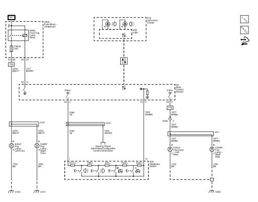
Fig. 8: Fog Lamps
FOG LIGHTS WIRING SCHEMATICS (Encore)
Fog Lamps
.jpg)
Fig. 9: Fog Lamps
EXTERIOR LIGHTS WIRING SCHEMATICS (ENCORE)
Park, Turn, Hazard and Brake Lamp Controls, and Indicators
.jpg)
Fig. 10: Park, Turn, Hazard and Brake Lamp Controls, and Indicators
Park, Repeater and Front Turn Lamps
.jpg)
Fig. 11: Park, Repeater and Front Turn Lamps
Tail, Stop and Rear Turn Signal Lamps
.jpg)
Fig. 12: Tail, Stop and Rear Turn Signal Lamps
License Plate and Backup Lamps
.jpg)
Fig. 13: License Plate and Backup Lamps
EXTERIOR LIGHTS WIRING SCHEMATICS (Encore)
Park, Turn, Hazard and Brake Lamp Controls, and Indicators
.jpg)
Fig. 14: Park, Turn, Hazard and Brake Lamp Controls, and Indicators
Park, Repeater and Front Turn Lamps
.jpg)
Fig. 15: Park, Repeater and Front Turn Lamps
Tail, Stop and Rear Turn Signal Lamps
.jpg)
Fig. 16: Tail, Stop and Rear Turn Signal Lamps
License Plate and Backup Lamps
.jpg)
Fig. 17: License Plate and Backup Lamps
INTERIOR LIGHTS WIRING SCHEMATICS (ENCORE)
Dome, Sunshades, and Rear Compartment Lamps
.jpg)
Fig. 18: Dome, Sunshades, and Rear Compartment Lamps
INTERIOR LIGHTS WIRING SCHEMATICS (Encore)
Dome, Sunshades, and Rear Compartment Lamps
.jpg)
Fig. 19: Dome, Sunshades, and Rear Compartment Lamps
INTERIOR LIGHTS DIMMING WIRING SCHEMATICS (ENCORE)
Controls, and Instrument Panel, Steering Wheel Switches
.jpg)
Fig. 20: Controls, and Instrument Panel, Steering Wheel Switches
Door, Sunroof, Instrument Panel Switches, and Accent Lamps
.jpg)
Fig. 21: Door, Sunroof, Instrument Panel Switches, and Accent Lamps
Window Switches
.jpg)
Fig. 22: Window Switches
INTERIOR LIGHTS DIMMING WIRING SCHEMATICS (Encore)
Controls, Headlamp, Instrument Panel, and Steering Wheel Switches
.jpg)
Fig. 23: Controls, Headlamp, Instrument Panel, and Steering Wheel Switches
Door, Sunroof, Mirror, and Instrument Panel Switches
.jpg)
Fig. 24: Door, Sunroof, Mirror, and Instrument Panel Switches
SPECIFICATIONS
Fastener Tightening Specifications
.jpg)
Lighting System - DTC Index
DIAGNOSTIC CODE INDEX
.jpg)
.jpg)
READ NEXT:
 Schematic wiring diagrams
SPECIFICATIONS
FASTENER TIGHTENING SPECIFICATIONS
Fastener Tightening Specifications
Adhesives, Fluids, Lubricants, and Sealers
SCHEMATIC WIRING DIAGRAMS
INSIDE REARVIEW MIRROR WIRING SCHEMATICS (
Mirrors - Diagnostic information and procedures
DTC B154A OR B154B: Mirror internal malfunction
DIAGNOSTIC CODE INDEX
Diagnostic Instructions
Perform the Diagnostic System Check - Vehicle prior to using this
diagnostic procedure.
Review Stra
SEE MORE:
Seat heating and cooling - Description and operation
HEATED SEATS DESCRIPTION AND OPERATION
Heated Seat Components
The driver and passenger heated seats consist of the following components:
Left heated seat switch
Right heated seat switch
HVAC control module
Seat memory control module or seat heating control module
Driver seat cushion heating el
Engine replacement
Engine replacement - Removal Procedure
Remove the battery and battery tray. Refer to Battery Tray Replacement .
Relieve the fuel system pressure. Refer to Fuel Pressure Relief .
Recover the refrigerant. Refer to Refrigerant Recovery and Recharging
(R-134a) .
Remove the front tire and wheel as
