Buick Encore: Seat heating and cooling - Repair instructions
Buick Encore 2012-2019 Service Manual / Accessories & Equipment / Seat Heating and Cooling / Seat heating and cooling - Repair instructions
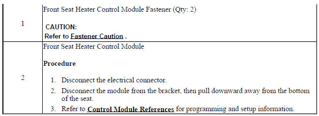
FRONT SEAT HEATER CONTROL MODULE REPLACEMENT
Fig. 3: Front Seat Heater Control Module
Front Seat Heater Control Module Replacement

DRIVER OR PASSENGER SEAT BACK CUSHION HEATER REPLACEMENT
.gif)
Fig. 4: Driver Or Passenger Seat Back Cushion Heater
Driver or Passenger Seat Back Cushion Heater Replacement
.jpg)
.jpg)
DRIVER OR PASSENGER SEAT CUSHION HEATER REPLACEMENT
Fig. 5: Driver Or Passenger Seat Cushion Heater
Driver or Passenger Seat Cushion Heater Replacement
.jpg)
.jpg)
READ NEXT:
 Seat heating and cooling - Description and operation
HEATED SEATS DESCRIPTION AND OPERATION
Heated Seat Components
The driver and passenger heated seats consist of the following components:
Left heated seat switch
Right heated seat switch
HVAC contr
Secondary and Configurable Customer Controls
Schematic wiring diagrams
STEERING WHEEL SECONDARY/CONFIGURABLE CONTROL WIRING SCHEMATICS
(ENCORE)
Steering Wheel Control System
Fig. 1: Steering Wheel Control System
STEERING WHEEL SECONDARY/CONFIG
Secondary and Configurable Customer Controls - Diagnostic information and
procedures
DTC B1405: Control module voltage reference output 2
DIAGNOSTIC CODE INDEX
DTC B1405: CONTROL MODULE VOLTAGE REFERENCE OUTPUT 2
Diagnostic Instructions
Perform the Diagnostic System Check - Vehicl
SEE MORE:
Wipers and washers - Repair instructions
WINDSHIELD WIPER AND WASHER SWITCH REPLACEMENT (ENCORE)
Fig. 8: Windshield Wiper And Washer Switch
Windshield Wiper and Washer Switch Replacement (Encore)
WINDSHIELD WIPER AND WASHER SWITCH REPLACEMENT (Encore)
Fig. 9: Windshield Wiper And Washer Switch
Windshield Wiper and Washer Switch Repla
Repair instructions
Front wheel drive intermediate shaft replacement (LUV
WITH MH8 OR MH5)
Fig. 1: Front Wheel Drive Intermediate Shaft
Front Wheel Drive Intermediate Shaft Replacement (LUV with MH8 or MH5)
FRONT WHEEL DRIVE INTERMEDIATE SHAFT BRACKET REPLACEMENT (LUV WITH MH8
OR MH5)
Fig. 2: Front Wheel Drive
© 2020-2026 Copyright www.bencore2.com
