Buick Encore: Vehicle access - Diagnostic information and procedures
DTC B252C: Child security lock switch circuit
DIAGNOSTIC CODE INDEX
.jpg)
Diagnostic Instructions
- Perform the Diagnostic System Check - Vehicle prior to using this diagnostic procedure.
- Review Strategy Based Diagnosis for an overview of the diagnostic approach.
- Diagnostic Procedure Instructions provides an overview of each diagnostic category.
DTC Descriptor
DTC B252C 00
Child Security Lock Switch Circuit
Diagnostic Fault Information
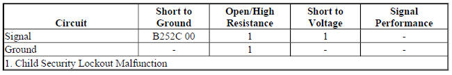
Circuit/System Description
The Body Control Module monitors the voltage level in the child security door lockout switch signal circuit, when the switch is in the open position the voltage in the signal circuit will be equal to the B+ voltage level.
When the child security door lockout switch is pressed, voltage within the signal circuit drops and the Body Control Module will detect the voltage drop and will energize the Door Lock relay to disable the interior rear door handles.
Conditions for Running the DTC
The system voltage is 9-16 V.
Conditions for Setting the DTC
The Body Control Module has detected a short to ground on the child security lockout switch signal circuit for greater than 60 seconds.
Action Taken When the DTC Sets
- The interior rear door handles will always be disabled or will not lockout depending upon the latch states when the fault occurred
- The Body Control Module will ignore the input from the lockout switch.
Conditions for Clearing the DTC
- The DTC will be current for as long as the fault is present.
- When the fault is no longer present, the DTC will be a history DTC.
- A history DTC will clear after 50 ignition cycles.
Reference Information
Schematic Reference
Door Lock/Indicator Schematics (Encore), Door Lock/Indicator Schematics (Encore)
Connector End View Reference
WIRING SYSTEMS AND POWER MANAGEMENT - COMPONENT CONNECTOR END VIEWS - INDEX - ENCORE WIRING SYSTEMS AND POWER MANAGEMENT - COMPONENT CONNECTOR END VIEWS - INDEX - Encore
Description and Operation
Power Door Locks Description and Operation
Electrical Information Reference
- Circuit Testing
- Connector Repairs
- Testing for Intermittent Conditions and Poor Connections
- Wiring Repairs
Scan Tool Reference
Control Module References for scan tool information
Circuit/System Verification
- Ignition ON.
- Verify the scan tool Left Rear Child Security Lock Switch and Right Rear Child Security Lock Switch parameters change between Inactive and Active when pressing and depressing the child security lockout switch.
- If the parameters do not change
Refer to Circuit/System Testing.
- If the parameters change
- All OK.
Circuit/System Testing
- Ignition OFF and all vehicle systems OFF, disconnect the harness connector at the S48E Multifunction Switch-Center Console. It may take up to 2 minutes for all vehicle systems to power down.
- Test for less than 10 ohms between the ground circuit terminal 9 and ground.
- If 10 ohms or greater
- Ignition OFF.
- Test for less than 2 ohms in the ground circuit end to end.
- If 2 ohms or greater, repair the open/high resistance in the circuit.
- If less than 2 ohms, repair the open/high resistance in the ground connection.
- If less than 10 ohms
- Ignition ON.
- Test for greater than 10 V between the signal circuit terminal 3 and ground.
- If 10 V or less
- Ignition OFF, disconnect the harness connector at the K9 Body Control Module.
- Test for infinite resistance between the signal circuit and ground.
- If less than infinite resistance, repair the short to ground on the circuit
- Test for less than 2 ohms in the signal circuit end to end.
- If 2 ohms or greater, repair the open/high resistance in the circuit.
- If less than 2 ohms, replace the K9 Body Control Module.
- If greater than 10 V
- Test or replace the S48E Multifunction Switch-Center Console.
Component Testing
- Ignition OFF, disconnect the harness connector at the S48E Multifunction Switch-Center Console.
- Test for infinite resistance between the signal terminal 3 and the ground terminal 9 with the switch in the open position.
- If less than infinite resistance
Replace the S48E Multifunction Switch-Center Console.
- If infinite resistance
- Test for less than 3 ohms between the signal terminal 3 and the ground terminal 9 with the switch in the closed position.
- If 3 ohms or greater
Replace the S48E Multifunction Switch-Center Console.
- If less than 3 ohms
- All OK
Repair Instructions
Perform the Diagnostic Repair Verification after completing the repair.
- Instrument Panel Multifunction Switch Replacement (Encore)
- Control Module References for the Body Control Module replacement, programming and setup
DTC B3125, B3130, OR B3135: Driver door only unlock/all doors lock/unlock
Diagnostic Instructions
- Perform the Diagnostic System Check - Vehicle prior to using this diagnostic procedure.
- Review Strategy Based Diagnosis for an overview of the diagnostic approach.
- Diagnostic Procedure Instructions provides an overview of each diagnostic category.
DTC Descriptors
DTC B3125
Driver Door Only Unlock Circuit
DTC B3130
All Doors Unlock Circuit
DTC B3135
All Doors Lock Circuit
For symptom byte information refer to: Symptom Byte List
Diagnostic Fault Information
.jpg)
.jpg)
Circuit/System Description
The body control module (BCM) controls the driver and passenger door latches. When the BCM receives a driver door unlock, passenger door unlock or all door lock command, it will provide voltage to the appropriate door lock circuits and ground to the opposite door lock circuits causing the actuator to perform the lock or unlock function.
Conditions for Running the DTC
When the output is actively being requested by the BCM.
Conditions for Setting the DTC
B3125 02, B3130 02 and B3135 02
- A short to ground or an open/high resistance in the BCM B+ circuit.
- The BCM detects a short to ground on a door latch control circuit.
Action Taken When the DTC Sets
The power door locks will be inoperative
Conditions for Clearing the DTC
- The DTC will be current for as long as the fault is present.
- When the fault is no longer present, the DTC will be a history DTC.
- A history DTC will clear after 50 ignition cycles.
Reference Information
Schematic Reference
- Door Lock/Indicator Schematics (Encore), Door Lock/Indicator Schematics (Encore)
- Body Control System Schematics (Encore) , Body Control System Schematics (Encore)
Connector End View Reference
WIRING SYSTEMS AND POWER MANAGEMENT - COMPONENT CONNECTOR END VIEWS - INDEX - ENCORE WIRING SYSTEMS AND POWER MANAGEMENT - COMPONENT CONNECTOR END VIEWS - INDEX - Encore
Description and Operation
Power Door Locks Description and Operation
Electrical Information Reference
- Circuit Testing
- Connector Repairs
- Testing for Intermittent Conditions and Poor Connections
- Wiring Repairs
Scan Tool Reference
Control Module References for scan tool information
Circuit/System Verification
- Ignition ON.
- Verify all vehicle doors LOCK and UNLOCK when commanding the All Doors Lock/Unlock with a scan tool.
- If only the driver door LOCK or UNLOCK functions do not work
Refer to Power Door Locks Malfunction.
- If one or more, but not all, passenger door LOCK or UNLOCK functions do not work Refer to Power Door Locks Malfunction.
- If all door LOCK and UNLOCK functions do not work
Refer to Circuit/System Testing
- If the LOCK and UNLOCK function for all doors works
- All OK.
Circuit/System Testing
- Ignition OFF, disconnect the X2 harness connector at the K9 Body Control Module, ignition ON.
- Verify a test lamp illuminates between the B+ circuit terminal 4 and ground.
If the test lamp does not illuminate and the circuit fuse is good
- Ignition OFF.
- Test for less than 2 ohms in the B+ circuit end to end.
- If 2 ohms or greater, repair the open/high resistance in the circuit.
- If less than 2 ohms, verify the fuse is not open and there is voltage at the fuse.
- If the test lamp does not illuminate and the circuit fuse is open
- Ignition OFF.
- Test for infinite resistance between the B+ circuit and ground.
- If less than infinite resistance, repair the short to ground on the circuit.
- If infinite resistance
- Disconnect the harness connector at each of the A23 Door Latch Assemblies.
- Test for infinite resistance between each control circuit and ground.
- If less than infinite resistance, repair the short to ground on the circuit.
- If infinite resistance, replace the appropriate A23 Door Latch Assembly.
- If the test lamp illuminates
- Ignition OFF, connect the X2 harness connector at the K9 Body Control Module. Disconnect the harness connector at the A23D Door Latch Assembly-Driver, ignition ON.
NOTE:
Leaving the DMM connected between a control circuit and ground for greater than 20 seconds will cause the K9 Body Control Module to interpret the test as a system fault and will cause the voltage on the control circuit to drop to 0 V. If the voltage drops to 0 V, operate the door locks using the door lock switch to restore the voltage for testing.
- Test for greater than 5 V between the control circuit terminal 2 and ground.
- If 5 V or less
- Ignition OFF, disconnect the X6 harness connector at the K9 Body Control Module.
- Test for infinite resistance between the control circuit terminal listed below and ground:
- Control circuit terminal 1 X6
- Control circuit terminal 2 X6
- Control circuit terminal 4 X6
- If less than infinite resistance, repair the short to ground on the circuit.
- If infinite resistance, replace the K9 Body Control Module.
- If greater than 5 V
- Verify that a test lamp does not illuminate between the control circuit terminal 2 and ground
- If the test lamp illuminates
- Ignition OFF, disconnect the X6 harness connector at the K9 Body Control Module
- Test for less than 1 V between the control circuit terminal listed below and ground:
- Control circuit terminal 1 X6
- Control circuit terminal 2 X6
- Control circuit terminal 4 X6
- If greater than 1 V, repair the short to voltage on the circuit.
- If less than 1 V, replace the K9 Body Control Module.
- If the test lamp does not illuminate
- Replace the K9 Body Control Module.
Component Testing
- Ignition OFF, disconnect the harness connector at the appropriate A23 Door Latch Assembly.
- Install a 25 A fused jumper wire between one of the control terminals and 12 V. Momentarily install a jumper wire between the other control terminal and ground. Reverse the jumper wires at least two times, the A23 Door Latch Assembly should perform the LOCK and UNLOCK function.
- If the actuator does not perform the LOCK and UNLOCK function
Replace the A23 Door Latch Assembly.
- If the actuator performs the LOCK and UNLOCK function
- All OK
Repair Instructions
Perform the Diagnostic Repair Verification after completing the repair.
- Front Side Door Latch Replacement
- Rear Side Door Latch Replacement
- Control Module References for BCM replacement, programming and setup
DTC B3140, B3145, B3150, OR B3155: Door lock/unlock switch
Diagnostic Instructions
- Perform the Diagnostic System Check - Vehicle prior to using this diagnostic procedure.
- Review Strategy Based Diagnosis for an overview of the diagnostic approach.
- Diagnostic Procedure Instructions provides an overview of each diagnostic category
DTC Descriptors
DTC B3140 00
Driver Door Unlock Switch Circuit
DTC B3145 00
Passenger Door Unlock Switch Circuit
DTC B3150 00
Driver Front Door Lock Switch Circuit
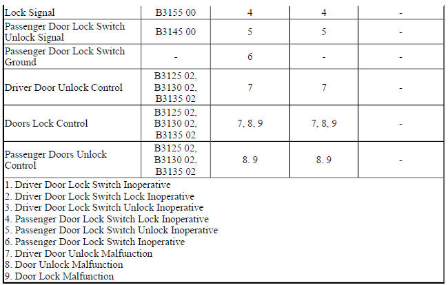
DTC B3155 00
Passenger Front Door Lock Switch Circuit
Diagnostic Fault Information
.jpg)
.jpg)
Circuit/System Description
The body control module (BCM) supplies a 12 V signal to each of the door lock and door unlock signal circuits.
When the door lock switches are in the open position, the voltage level in the signal circuit will be near 12 V.
When any door lock switch is pressed to the lock or unlock position, the voltage level in the appropriate signal circuit will drop to 0 V and the BCM will detect the voltage drop and command the door latches to perform the requested lock or unlock command.
Conditions for Running the DTC
The system voltage is 9-16 V.
Conditions for Setting the DTC
B3140 00
The BCM detects short to ground in the driver unlock signal circuit for greater than 30 seconds.
B3145 00
The BCM detects short to ground in the passenger unlock signal circuit for greater than 30 seconds.
B3150 00
The BCM detects a short to ground in the driver lock signal circuit for greater than 30 seconds.
B3155 00
The BCM detects a short to ground in the passenger lock signal circuit for greater than 30 seconds.
Action Taken When the DTC Sets
B3140 00
The BCM will ignore the unlock signal and the doors will not unlock when using the driver door unlock switch.
B3145 00
The BCM will ignore the unlock signal and the doors will not unlock when using the passenger door unlock switch.
B3150 00
The BCM will ignore the lock signal and the doors will not lock when using the driver door lock switch.
B3155 00
The BCM will ignore the lock signal and the doors will not lock when using the passenger door lock switch.
Conditions for Clearing the DTC
- The DTC will be current for as long as the fault is present.
- When the fault is no longer present, the DTC will be a history DTC.
- A history DTC will clear after 50 ignition cycles.
Reference Information
Schematic Reference
Door Lock/Indicator Schematics (Encore), Door Lock/Indicator Schematics (Encore)
Connector End View Reference
WIRING SYSTEMS AND POWER MANAGEMENT - COMPONENT CONNECTOR END VIEWS - INDEX - ENCORE WIRING SYSTEMS AND POWER MANAGEMENT - COMPONENT CONNECTOR END VIEWS - INDEX - Encore
Description and Operation
Power Door Locks Description and Operation
Electrical Information Reference
- Circuit Testing
- Connector Repairs
- Testing for Intermittent Conditions and Poor Connections
- Wiring Repairs
Scan Tool Reference
Control Module References for scan tool information
Circuit/System Verification
- Ignition ON.
- Verify the scan tool Driver Door Lock Switch parameter changes from Inactive to Lock and Unlock when pushing the appropriate switch on the S13D Door Lock Switch - Driver.
- If the parameter does not change
Refer to Circuit/System Testing - Driver Door Lock Switch Malfunction.
- If the parameter changes
- Verify the scan tool Passenger Door Lock Switch parameter changes from Inactive to Lock and Unlock when pushing the appropriate switch on the S13P Door Lock Switch - Passenger.
- If the parameter does not change
Refer to Circuit/System Testing - Passenger Door Lock Switch Malfunction.
- If the parameter changes
- All OK.
Circuit/System Testing
Driver Door Lock Switch Malfunction
- Ignition OFF and all vehicle systems OFF, disconnect the harness connector at the S13D Door Lock Switch - Driver. It may take up to 2 minutes for all vehicle systems to power down.
- Test for less than 10 ohms between the ground circuit terminal 3 and ground.
- If 10 ohms or greater
- Ignition OFF.
- Test for less than 2 ohms in the ground circuit end to end.
- If 2 ohms or greater, repair the open/high resistance in the circuit.
- If less than 2 ohms, repair the open/high resistance in the ground connection.
- If less than 10 ohms
- Ignition ON.
- Verify the scan tool Driver Door Lock Switch parameter is Inactive.
If not Inactive
- Ignition OFF, disconnect the harness connector at the K9 Body Control Module.
- Test for infinite resistance between the signal circuit terminal 4 and ground.
- If less than infinite resistance, repair the short to ground on the circuit.
- Test for infinite resistance between the signal circuit terminal 2 and ground.
- If less than infinite resistance, repair the short to ground on the circuit.
- If infinite resistance, replace the K9 Body Control Module.
- If Inactive
- Install a 3 A fused jumper wire between the signal circuit terminal 4 and the ground circuit terminal 3.
- Verify the scan tool Driver Door Lock Switch parameter is Lock.
- If not Lock
- Ignition OFF, remove the 3 A fused jumper wire, disconnect the harness connector at the K9 Body Control Module, ignition ON.
- Test for less than 1 V between the signal circuit and ground.
- If 1 V or greater, repair the short to voltage on the circuit.
- If less than 1 V
- Test for less than 2 ohms in the signal circuit end to end.
- If 2 ohms or greater, repair the open/high resistance in the circuit.
- If less than 2 ohms, replace the K9 Body Control Module.
- If Lock
- Install a 3 A fused jumper wire between the signal circuit terminal 2 and the ground circuit terminal 3.
- Verify the scan tool Driver Door Lock Switch parameter is Unlock.
- If not Unlock
- Ignition OFF, 3 A fused jumper wire, disconnect the harness connector at the K9 Body Control Module, ignition ON.
- Test for less than 1 V between the signal circuit and ground.
- If 1 V or greater, repair the short to voltage on the circuit.
- If less than 1 V
- Test for less than 2 ohms in the signal circuit end to end.
- If 2 ohms or greater, repair the open/high resistance in the circuit.
- If less than 2 ohms, replace the K9 Body Control Module.
- If Unlock
- Test or replace the S13D Door Lock Switch - Driver.
Passenger Door Lock Switch Malfunction
- Ignition OFF and all vehicle systems OFF, disconnect the harness connector at the S13P Door Lock Switch - Passenger. It may take up to 2 minutes for all vehicle systems to power down.
- Test for less than 10 ohms between the ground circuit terminal 3 and ground.
If 10 ohms or greater
- Ignition OFF.
- Test for less than 2 ohms in the ground circuit end to end.
- If 2 ohms or greater, repair the open/high resistance in the circuit.
- If less than 2 ohms, repair the open/high resistance in the ground connection.
- If less than 10 ohms
- Ignition ON.
- Verify the scan tool Passenger Door Lock Switch parameter is Inactive.
- If not Inactive
- Ignition OFF, disconnect the harness connector at the K9 Body Control Module.
- Test for infinite resistance between the signal circuit terminal 4 and ground.
- If less than infinite resistance, repair the short to ground on the circuit.
- Test for infinite resistance between the signal circuit terminal 2 and ground.
- If less than infinite resistance, repair the short to ground on the circuit.
- If infinite resistance, replace the K9 Body Control Module.
- If Inactive
- Install a 3 A fused jumper wire between the signal circuit terminal 4 and the ground circuit terminal 3.
- Verify the scan tool Passenger Door Lock Switch parameter is Lock.
- If not Lock
- Ignition OFF, 3 A fused jumper wire, disconnect the harness connector at the K9 Body Control Module, ignition ON.
- Test for less than 1 V between the signal circuit and ground.
- If 1 V or greater, repair the short to voltage on the circuit.
- If less than 1 V
- Test for less than 2 ohms in the signal circuit end to end.
- If 2 ohms or greater, repair the open/high resistance in the circuit.
- If less than 2 ohms, replace the K9 Body Control Module.
- If Lock
- Install a 3 A fused jumper wire between the signal circuit terminal 2 and the ground circuit terminal 3.
- Verify the scan tool Passenger Door Lock Switch parameter is Unlock.
If not Unlock
- Ignition OFF, 3 A fused jumper wire, disconnect the harness connector at the K9 Body Control Module, ignition ON.
- Test for less than 1 V between the signal circuit and ground.
- If 1 V or greater, repair the short to voltage on the circuit.
- If less than 1 V
- Test for less than 2 ohms in the signal circuit end to end.
- If 2 ohms or greater, repair the open/high resistance in the circuit.
- If less than 2 ohms, replace the K9 Body Control Module.
- If Unlock
- Test or replace the S13P Door Lock Switch - Passenger.
Component Testing
Driver Door Lock Switch
- Ignition OFF, disconnect the harness connector at the S13D Door Lock Switch - Driver.
- Test for infinite resistance between the signal terminal 2 and the ground terminal 3 with the switch in the center position.
- If less than infinite resistance
Replace the S13D Door Lock Switch - Driver.
- If infinite resistance
- Test for infinite resistance between the signal terminal 4 and the ground terminal 3 with the switch in the center position.
- If less than infinite resistance
Replace the S13D Door Lock Switch - Driver
- If infinite resistance
- Test for less than 2 ohms between the signal terminal 4 and the ground terminal 3 with the switch in the Lock position
- If 2 ohms or greater
Replace the S13D Door Lock Switch - Driver.
- If less than 2 ohms
- Test for less than 2 ohms between the signal terminal 2 and the ground terminal 3 with the switch in the Unlock position.
- If 2 ohms or greater
Replace the S13D Door Lock Switch - Driver.
- If less than 2 ohms
- All OK
Passenger Door Lock Switch
- Ignition OFF, disconnect the harness connector at the S13P Door Lock Switch - Passenger.
- Test for infinite resistance between the signal terminal 2 and the ground terminal 3 with the switch in the center position
- If less than infinite resistance
Replace the S13P Door Lock Switch - Passenger.
- If infinite resistance
- Test for infinite resistance between the signal terminal 4 and the ground terminal 3 with the switch in the center position.
- If less than infinite resistance
Replace the S13P Door Lock Switch - Passenger
- If infinite resistance
- Test for less than 2 ohms between the signal terminal 4 and the ground terminal 3 with the switch in the Lock position.
- If 2 ohms or greater
Replace the S13P Door Lock Switch - Passenger.
- If less than 2 ohms
- Test for less than 2 ohms between the signal terminal 2 and the ground terminal 3 with the switch in the Unlock position.
- If 2 ohms or greater
Replace the S13P Door Lock Switch - Passenger.
- If less than 2 ohms
- All OK
Repair Instructions
Perform the Diagnostic Repair Verification after completing the repair.
- Door Lock Switch Replacement - Driver Side (Encore), Door Lock Switch Replacement - Driver Side (Encore)
- Door Lock Switch Replacement - Passenger Front (Encore), Door Lock Switch Replacement - Passenger Front (Encore)
- Control Module References for BCM replacement, programming and setup
DTC B3245: Rear cargo door lock actuator circuit
Diagnostic Instructions
- Perform the Diagnostic System Check - Vehicle prior to using this diagnostic procedure.
- Review Strategy Based Diagnosis for an overview of the diagnostic approach.
- Diagnostic Procedure Instructions provides an overview of each diagnostic category.
DTC Descriptors
DTC B3245
Rear Cargo Door Lock Actuator Circuit
For symptom byte information refer to: Symptom Byte List
Diagnostic Fault Information
.jpg)
Circuit/System Description
When the body control module (BCM) receives a liftgate release command, it will provide voltage to one side of the relay and ground to the other side of the relay. This will energize the relay causing the switch side of the relay to close and will then provide B+ voltage to the liftgate latch.
Conditions for Running the DTC
- The system voltage is 9-16 V.
- When the relay is actively commanded by the BCM.
Conditions for Setting the DTC
B3245 01
The BCM detects a short to voltage in the liftgate unlatch relay control circuit.
B3245 02
The BCM detects a short to ground in the liftgate unlatch relay control circuit.
Action Taken When the DTC Sets
The liftgate latch will be inoperative.
Conditions for Clearing the DTC
- The DTC will be current for as long as the fault is present.
- When the fault is no longer present, the DTC will be a history DTC.
- A history DTC will clear after 50 ignition cycles.
Reference Information
Schematic Reference
Release Systems Schematics (Encore), Release Systems Schematics (Encore)
Connector End View Reference
WIRING SYSTEMS AND POWER MANAGEMENT - COMPONENT CONNECTOR END VIEWS - INDEX - ENCORE WIRING SYSTEMS AND POWER MANAGEMENT - COMPONENT CONNECTOR END VIEWS - INDEX - Encore
Description and Operation
Rear Hatch/Gate Description and Operation
Electrical Information Reference
- Circuit Testing
- Connector Repairs
- Testing for Intermittent Conditions and Poor Connections
- Wiring Repairs
Scan Tool Reference
Control Module References for scan tool information
Circuit/System Verification
- Ignition ON.
- Verify the M30 Liftgate Latch functions when commanding the Liftgate Unlatch with a scan tool.
- If the M30 Liftgate Latch does not function
Refer to Circuit/System Testing.
- If the M30 Liftgate Latch does function
- All OK
Circuit/System Testing
- Ignition OFF, disconnect the KR95A Liftgate Unlatch Relay. Ignition ON.
- Connect a test lamp between the control circuit terminal 2 and ground.
- Verify the test lamp turns ON and OFF when commanding the Liftgate Unlatch with a scan tool.
- If the test lamp is always OFF
- Ignition OFF, remove the test lamp, disconnect the harness connector at the K9 Body Control Module.
- Test for infinite resistance between the control circuit and ground.
- If less than infinite resistance, repair the short to ground on the circuit.
- If infinite resistance
- Test for less than 2 ohms in the control circuit end to end.
- If 2 ohms or greater, repair the open/high resistance in the circuit.
- If less than 2 ohms, replace the K9 Body Control Module.
- If the test lamp is always ON
- Ignition OFF, remove the test lamp, disconnect the harness connector at the K9 Body Control Module, ignition ON.
- Test for less than 1 V between the control circuit and ground.
- If 1 V or greater, repair the short to voltage on the circuit
- If less than 1 V, replace the K9 Body Control Module
- If the test lamp turns ON and OFF
- Connect a test lamp between the control circuit terminal 1 and B+.
- Verify the test lamp turns ON and OFF when commanding the Liftgate Unlatch with a scan tool.
- If the test lamp is always OFF
- Ignition OFF, remove the test lamp, disconnect the harness connector at the K9 Body Control Module, ignition ON.
- Test for less than 1 V between the control circuit and ground.
- If 1 V or greater, repair the short to voltage on the circuit.
- If less than 1 V
- Ignition OFF.
- Test for less than 2 ohms in the control circuit end to end.
- If 2 ohms or greater, repair the open/high resistance in the circuit.
- If less than 2 ohms, replace the K9 Body Control Module.
- If the test lamp is always ON
- Ignition OFF, remove the test lamp, disconnect the harness connector at the K9 Body Control Module.
- Test for infinite resistance between the control circuit and ground.
- If less than infinite resistance, repair the short to ground on the circuit.
- If infinite resistance, replace the K9 Body Control Module.
- If the test lamp turns ON and OFF
- Test or replace the KR95A Liftgate Unlatch Relay.
Component Testing
Relay Test
- Ignition OFF, disconnect the KR95A Liftgate Unlatch Relay.
- Test for 60-200 ohms between terminals 85 and 86.
- If less than 60 or greater than 200
Replace the KR95A Liftgate Unlatch Relay.
- If between 60-200 ohms
- Test for infinite resistance between the terminals listed below:
- 30 and 86
- 30 and 87
- 30 and 85
- 85 and 87
- If less than infinite resistance
Replace the KR95A Liftgate Unlatch Relay.
- If infinite resistance
- Install a 3 A fused jumper wire between relay terminal 85 and 12 V. Install a jumper wire between relay terminal 86 and ground.
- Test for less than 2 ohms between terminals 30 and 87.
- If 2 ohms or greater
Replace the KR95A Liftgate Unlatch Relay.
- If less than 2 ohms
- All OK
Repair Instructions
Perform the Diagnostic Repair Verification after completing the repair.
- Relay Replacement (Within an Electrical Center) , Relay Replacement (Attached to Wire Harness)
- Control Module References for BCM replacement, programming and setup
DTC B3930: Child security lock motors
Diagnostic Instructions
- Perform the Diagnostic System Check - Vehicle prior to using this diagnostic procedure.
- Review Strategy Based Diagnosis for an overview of the diagnostic approach.
- Diagnostic Procedure Instructions provides an overview of each diagnostic category
DTC Descriptors
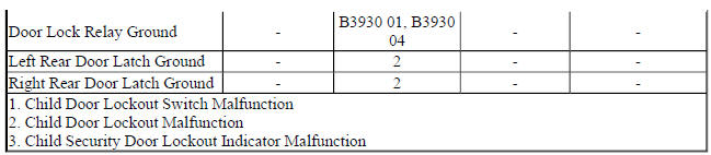
DTC B3930 01
Child Security Lock Motors Circuit Short to Battery
DTC B3930 02
Child Security Lock Motors Circuit Short to Ground
DTC B3930 04
Child Security Lock Motors Circuit Open
Diagnostic Fault Information
.jpg)
.jpg)
Circuit/System Description
The body control module controls the child security lock relay when it receives a command to lockout the rear doors. The relay will apply voltage to both child security circuits at the rear door latches to disable the interior rear door handles.
Conditions for Running the DTC
When the Door Lock relay is being actively commanded by the body control module.
Conditions for Setting the DTC
B3930 01
The body control module detects a short to voltage or an open/high resistance in the door lock security relay control circuit.
The body control module detects a an open/high resistance in the underhood fuse block ground circuit.
The body control module detects a short to ground or an open/high resistance in the body control module B+ circuit.
B3930 02
The BCM detects a short to ground in the door lock security relay control circuit.
B3930 04
The body control module detects a short to voltage or an open/high resistance in the door lock security relay control circuit.
The body control module detects a an open/high resistance in the underhood fuse block ground circuit.
The body control module detects a short to ground or an open/high resistance in the body control module B+ circuit.
Action Taken When the DTC Sets
- The interior rear door handles will always be disabled or will not lockout depending upon the latch states when the fault occurred
- The body control module will command the lockout indicator to flash ON and OFF for 30 seconds when the lockout switch is pressed to indicate a fault in the system.
Conditions for Clearing the DTC
- The DTC will be current for as long as the fault is present.
- When the fault is no longer present, the DTC will be a history DTC.
- A history DTC will clear after 50 ignition cycles
Reference Information
Schematic Reference
Door Lock/Indicator Schematics (Encore), Door Lock/Indicator Schematics (Encore)
Connector End View Reference
WIRING SYSTEMS AND POWER MANAGEMENT - COMPONENT CONNECTOR END VIEWS - INDEX - ENCORE WIRING SYSTEMS AND POWER MANAGEMENT - COMPONENT CONNECTOR END VIEWS - INDEX - Encore
Description and Operation
Power Door Locks Description and Operation
Electrical Information Reference
- Testing for Intermittent Conditions and Poor Connections
- Circuit Testing
- Wiring Repairs
- Connector Repairs
Scan Tool Reference
Control Module References for scan tool information
Circuit/System Verification
- Ignition ON.
- Verify both interior rear door handles do not open the rear doors when commanding the Child Security Lock Motors ON with a scan tool.
- If both interior door handles open the rear doors
Refer to Circuit/System Testing.
- If both interior door handles do not open the rear doors
- Verify both interior rear door handles will open the rear doors when commanding the Child Security Lock Motors OFF with a scan tool.
- If both interior door handles do not open the rear doors
Refer to Circuit/System Testing
- If both interior door handles open the rear doors
- All OK
Circuit/System Testing
- Ignition OFF and all vehicle systems OFF, disconnect the X2 harness connector at the X50A Fuse Block- Underhood. It may take up to 2 minutes for all vehicle systems to power down.
- Test for less than 10 ohms between the ground circuit terminal C5 and ground.
- If 10 ohms or greater
- Ignition OFF.
- Test for less than 2 ohms in the ground circuit end to end.
- If 2 ohms or greater, repair the open/high resistance in the circuit.
- If less than 2 ohms, repair the open/high resistance in the ground connection.
- If less than 10 ohms
- Ignition OFF, connect the X2 harness connector at the X50A Fuse Block-Underhood. Disconnect the X4 harness connector at the K9 Body Control Module, ignition ON.
- Verify that a test lamp does not illuminate between the control circuit terminal 8 and ground.
- If the test lamp illuminates
- Ignition OFF, remove the test lamp, disconnect the X2 harness connector at the X50A Fuse Block- Underhood.
- Test for less than 1 V between the K9 Body Control Module control circuit terminal 8 X4 and ground.
- If 1 V or greater, repair the short to voltage on the circuit.
- If less than 1 V, replace the X50A Fuse Block-Underhood.
- If the test lamp is not illuminated
- Connect a 3A fused jumper wire between the control circuit terminal 8 and B+.
- Listen for an audible click from the X50A Fuse Block-Underhood as the KR113 Child Security Lock Disable Relay activates.
- If the KR113 Child Security Lock Disable Relay does not activate
- Ignition OFF, remove the jumper wire, disconnect the X2 harness connector at the X50A Fuse Block-Underhood.
- Test for infinite resistance between the K9 Body Control Module control circuit terminal 8 X4 and ground.
- If less than Infinite resistance, repair the short to ground on the circuit.
- If infinite resistance
- Test for less than 2 ohms in the control circuit end to end.
- If 2 ohms or greater, repair the open/high resistance in the circuit.
- If less than 2 ohms, replace the X50A Fuse Block-Underhood.
- If the KR113 Child Security Lock Disable Relay activates
- Replace the K9 Body Control Module.
Repair Instructions
Perform the Diagnostic Repair Verification after completing the repair.
- Front Compartment Fuse Block Replacement
- Control Module References body control module replacement, programming and setup
SYMPTOMS - VEHICLE ACCESS
NOTE: The following steps must be completed before using the symptom tables.
- Perform the Diagnostic System Check - Vehicle , before using the Symptom Tables in order to verify that all of the following are true:
- There are no DTCs set
- The control modules can communicate via the serial data link
- Review the system operation in order to familiarize yourself with the system functions. Refer to the following systems description:
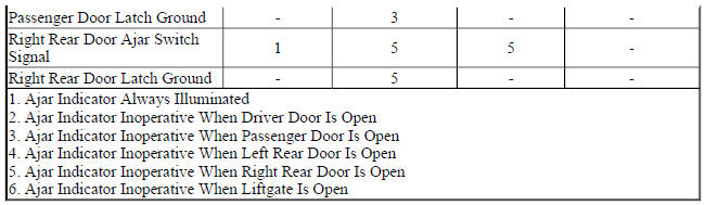
- Door Ajar Indicator Description and Operation
- Rear Hatch/Gate Description and Operation
- Power Door Locks Description and Operation
Visual/Physical Inspection
- Inspect for aftermarket devices which may affect the operation of the system. Refer to Checking Aftermarket Accessories .
- Inspect the easily accessible or visible system components for obvious damage or conditions which may cause the symptom.
Intermittent
Faulty electrical connections or wiring may be the cause of intermittent conditions. Refer to Testing for Intermittent Conditions and Poor Connections .
Symptom List
Refer to a symptom diagnostic procedure from the following list in order to diagnose the symptom:
- Power Door Child Lock Malfunction
- Door Ajar Indicator Malfunction
- Power Door Locks Malfunction
- Liftgate Release Malfunction
Fuel filler door release malfunction (NO8)
Diagnostic Instructions
- Perform the Diagnostic System Check - Vehicle prior to using this diagnostic procedure.
- Review Strategy Based Diagnosis for an overview of the diagnostic approach.
- Diagnostic Procedure Instructions provides an overview of each diagnostic category.
Diagnostic Fault Information
.jpg)
Circuit/System Description
The locking and unlocking of the fuel door is a function of the power door lock system. The fuel door lock actuator shares the circuit with the door latch unlock control circuit. The body control module (BCM), upon receipt of a lock switch lock or unlock signal, will switch the appropriate door latch, as well as a fuel door lock actuator control circuits to B+ voltage. The opposing side of the door latch and fuel door lock actuator control circuit is pulled to ground by the BCM through the other the door latch control circuits, along with the fuel door lock actuator, will lock or unlock as commanded.
Reference Information
Schematic Reference
Door Lock/Indicator Schematics (Encore), Door Lock/Indicator Schematics (Encore)
Connector End View Reference
WIRING SYSTEMS AND POWER MANAGEMENT - COMPONENT CONNECTOR END VIEWS - INDEX - ENCORE WIRING SYSTEMS AND POWER MANAGEMENT - COMPONENT CONNECTOR END VIEWS - INDEX - Encore
Description and Operation
Fuel Fill Door Description and Operation (NO8 Only)
Electrical Information Reference
- Circuit Testing
- Connector Repairs
- Testing for Intermittent Conditions and Poor Connections
- Wiring Repairs
Scan Tool Reference
- Control Module References for scan tool information
- Circuit/System Verification
- Ignition ON.
- Verify the M97 Fuel Door Lock Actuator does not release the fuel filler door when commanding the All Doors Lock/Unlock to Lock with a scan tool.
- If the M97 Fuel Door Lock Actuator releases the fuel filler door
Refer to Circuit/System Testing.
- If the M97 Fuel Door Lock Actuator does not release the fuel filler door
- Verify the M97 Fuel Door Lock Actuator releases the fuel filler door when commanding the All Doors Lock/Unlock to Unlock with a scan tool.
- If the M97 Fuel Door Lock Actuator does not release the fuel filler door
Refer to Circuit/System Testing.
- If the M97 Fuel Door Lock Actuator releases the fuel filler door
- All OK.
Circuit/System Testing
- Ignition OFF, disconnect the harness connector at the M97 Fuel Door Lock Actuator.
- Connect a test lamp between control circuit terminal 1 and control circuit terminal 2, ignition ON.
- Verify the test lamp turns ON when commanding the All Doors Lock/Unlock with a scan tool.
If the test lamp remains OFF during either of the commands
- Ignition OFF, remove the test lamp, disconnect the harness connector at the K9 Body Control Module.
- Test for infinite resistance between each control circuit and ground.
- If less than infinite resistance, repair the short to ground on the circuit.
- If infinite resistance, replace the K9 Body Control Module.
- Test for less than 2 ohms in each control circuit end to end.
- If 2 ohms or greater, repair the open/high resistance in the circuit.
- If less than 2 ohms, replace the K9 Body Control Module.
- If the test lamp turns ON during each of the commands
- Test or replace the M97 Fuel Door Lock Actuator.
Component Testing
Fuel Door Latch
- Ignition OFF, disconnect the harness connector at the M97 Fuel Door Lock Actuator.
- Install a 25 A fused jumper wire between one of the control terminals and 12 V. Momentarily install a jumper wire between the other control terminal and ground. Reverse the jumper wires at least two times, the M97 Fuel Door Lock Actuator should perform the LOCK and UNLOCK function.
- If the actuator does not perform the LOCK and UNLOCK function
Replace the M97 Fuel Door Lock Actuator.
- If the actuator performs the LOCK and UNLOCK function
- All OK
Repair Instructions
Perform the Diagnostic Repair Verification after completing the repair.
- Fuel Tank Filler Door Latch Housing Replacement (Encore) , Fuel Tank Filler Door Latch Housing Replacement (Encore)
- Control Module References for BCM replacement, programming and setup
Liftgate release malfunction
Diagnostic Instructions
- Perform the Diagnostic System Check - Vehicle prior to using this diagnostic procedure.
- Review Strategy Based Diagnosis for an overview of the diagnostic approach.
- Diagnostic Procedure Instructions provides an overview of each diagnostic category.
Diagnostic Fault Information
.jpg)
.jpg)
Circuit/System Description
The liftgate unlatch switch is an input to the body control module (BCM). The BCM supplies a 12 V signal to the liftgate unlatch switch and when the switch is pressed, signal circuit voltage goes low. When the BCM receives a liftgate release signal it will monitor the status to the door latches. If the vehicle doors are locked, the BCM will ignore the request, if the doors are unlocked, the BCM will supply voltage and ground to the liftgate release relay coil, energizing the relay. When the relay is energized, battery voltage flows through the closed contacts of the relay to the liftgate latch assembly which activates allowing for the liftgate to be raised to the open position.
Diagnostic Aids
An intermittent short to ground in the liftgate unlatch switch signal circuit may cause the BCM to command the liftgate to open if the vehicle is in park and the doors are unlocked. If the vehicle has a history of the liftgate opening unexpectedly, inspect the point where the wires enter the liftgate unlatch switch for corrosion or evidence of water intrusion.
Reference Information
Schematic Reference
Release Systems Schematics (Encore), Release Systems Schematics (Encore)
Connector End View Reference
WIRING SYSTEMS AND POWER MANAGEMENT - COMPONENT CONNECTOR END VIEWS - INDEX - ENCORE WIRING SYSTEMS AND POWER MANAGEMENT - COMPONENT CONNECTOR END VIEWS - INDEX - Encore
Description and Operation
Rear Hatch/Gate Description and Operation
Electrical Information Reference
- Circuit Testing
- Connector Repairs
- Testing for Intermittent Conditions and Poor Connections
- Wiring Repairs
Scan Tool Reference
Control Module References for scan tool information
Circuit/System Verification
- Ignition ON.
- Verify the scan tool Trunk Lid/Liftgate Window Exterior Unlatch Switch parameter changes between Inactive and Active when pressing the S46B Liftgate Unlatch Switch.
- If the parameter does not change
Refer to Circuit/System Testing - Liftgate Release Switch Inoperative.
- If the parameter changes
NOTE:
Verify all doors have been commanded UNLOCK with a scan tool prior to commanding the liftgate to unlatch
- Verify the M30 Liftgate Latch functions when commanding the Liftgate Unlatch with a scan tool.
- If the M30 Liftgate Latch does not UNLATCH
Refer to Circuit/System Testing - Liftgate Latch Inoperative
- If the M30 Liftgate Latch does UNLATCH
- All OK.
Circuit/System Testing
Liftgate Release Switch Inoperative
- Ignition OFF and all vehicle systems OFF, disconnect the harness connector at the S46B Liftgate Unlatch Switch. It may take up to 2 minutes for all vehicle systems to power down.
- Test for less than 10 ohms between the ground circuit terminal 2 and ground.
- If 10 ohms or greater
- Ignition OFF.
- Test for less than 2 ohms in the ground circuit end to end.
- If 2 ohms or greater, repair the open/high resistance in the circuit.
- If less than 2 ohms, repair the open/high resistance in the ground connection.
- If less than 10 ohms
- Ignition ON.
- Verify the scan tool Trunk Lid/Liftgate Window Exterior Unlatch Switch parameter is Inactive.
- If not Inactive
- Ignition OFF, disconnect the harness connector at the K9 Body Control Module.
- Test for infinite resistance between the signal circuit terminal 1 and ground.
- If less than infinite resistance, repair the short to ground on the circuit.
- If infinite resistance, replace the K9 Body Control Module.
- If Inactive
- Install a 3 A fused jumper wire between the signal circuit terminal 1 and the ground circuit terminal 2.
- Verify the scan tool Trunk Lid/Liftgate Window Exterior Unlatch Switch parameter is Active
- If not Active
- Ignition OFF, remove the jumper wire, disconnect the harness connector at the K9 Body Control Module, ignition ON.
- Test for less than 1 V between the signal circuit and ground.
- If 1 V or greater, repair the short to voltage on the circuit.
- If less than 1 V
- Test for less than 2 ohms in the signal circuit end to end.
- If 2 ohms or greater, repair the open/high resistance in the circuit.
- If less than 2 ohms, replace the K9 Body Control Module.
- If Active
- Test or replace the S46B Liftgate Unlatch Switch.
Liftgate Latch Inoperative
- Ignition OFF, disconnect the KR95A Liftgate Unlatch Relay. Ignition ON.
- Verify a test lamp illuminates between the B+ circuit terminal 3 and ground.
- If the test lamp does not illuminate and the circuit fuse is good
- Ignition OFF.
- Test for less than 2 ohms in the B+ circuit end to end.
- If 2 ohms or greater, repair the open/high resistance in the circuit.
- If less than 2 ohms, verify the fuse is not open and there is voltage at the fuse.
- If the test lamp does not illuminate and the circuit fuse is open
- Ignition OFF.
- Test for infinite resistance between the B+ circuit and ground.
- If less than infinite resistance, repair the short to ground on the circuit.
- If infinite resistance
- Disconnect the harness connector at the M30 Liftgate Latch.
- Test for infinite resistance between the control circuit terminal 5 and ground.
- If less than infinite resistance, repair the short to ground on the circuit.
- If infinite resistance, replace the KR95A Liftgate Unlatch Relay
- If the test lamp illuminates
- Connect a test lamp between the control circuit terminal 2 and ground.
- Ignition ON, verify the test lamp turns ON and OFF when commanding the Liftgate Unlatch with a scan tool.
- If the test lamp is always OFF
- Ignition OFF, remove the test lamp, disconnect the harness connector at the K9 Body Control Module.
- Test for infinite resistance between the control circuit and ground.
- If less than infinite resistance, repair the short to ground on the circuit.
- If infinite resistance
- Test for less than 2 ohms in the control circuit end to end.
- If 2 ohms or greater, repair the open/high resistance in the circuit.
- If less than 2 ohms, replace the K9 Body Control Module.
- If the test lamp is always ON
- Ignition OFF, remove the test lamp, disconnect the harness connector at the K9 Body Control Module, ignition ON.
- Test for less than 1 V between the control circuit and ground.
- If 1 V or greater, repair the short to voltage on the circuit.
- If less than 1 V, replace the K9 Body Control Module.
- If the test lamp turns ON and OFF
- Connect a test lamp between the control circuit terminal 1 and B+.
- Verify the test lamp turns ON and OFF when commanding the Liftgate Unlatch with a scan tool.
- If the test lamp is always OFF
- Ignition OFF, remove the test lamp, disconnect the harness connector at the K9 Body Control Module, ignition ON.
- Test for less than 1 V between the control circuit and ground.
- If 1 V or greater, repair the short to voltage on the circuit.
- If less than 1 V
- Ignition OFF.
- Test for less than 2 ohms in the control circuit end to end.
- If 2 ohms or greater, repair the open/high resistance in the circuit.
- If less than 2 ohms, replace the K9 Body Control Module.
- If the test lamp is always ON
- Ignition OFF, remove the test lamp, disconnect the harness connector at the K9 Body Control Module.
- Test for infinite resistance between the control circuit and ground.
- If less than infinite resistance, repair the short to ground on the circuit.
- If infinite resistance, replace the K9 Body Control Module.
- If the test lamp turns ON and OFF
- Verify that a test lamp does not illuminate between the control circuit terminal 5 and ground.
- If the test lamp illuminates
Repair the short to voltage on the control circuit
- If the test lamp does not illuminate
- Ignition OFF and all vehicle systems OFF, disconnect the harness connector at the M30 Liftgate Latch. It may take up to 2 minutes for all vehicle systems to power down.
- Test for less than 10 ohms between the ground circuit terminal 1 and ground.
- If 10 ohms or greater
- Ignition OFF.
- Test for less than 2 ohms in the ground circuit end to end.
- If 2 ohms or greater, repair the open/high resistance in the circuit.
- If less than 2 ohms, repair the open/high resistance in the ground connection.
- If less than 10 ohms
- Connect the harness connector at the M30 Liftgate Latch
- Ignition ON, connect a 10 A fused jumper wire between the B+ circuit terminal 3 and the control circuit terminal 5.
- Verify the M30 Liftgate Latch is activated.
- If the M30 Liftgate Latch does not activate
- Ignition OFF, disconnect the harness connector at the M30 Liftgate Latch.
- Test for less than 2 ohms in the control circuit end to end.
- If 2 ohms or greater, repair the open/high resistance in the circuit.
- If less than 2 ohms, test or replace the M30 Liftgate Latch.
- If the M30 Liftgate Latch activates
- Test or replace the KR95A Liftgate Unlatch Relay.
Component Testing
Liftgate Latch
- Ignition OFF, disconnect the harness connector at the M30 Liftgate Latch.
- Install a 10 A fused jumper wire between the control terminal 3 and 12 V. Install a jumper wire between the ground terminal 1 and ground.
- Verify the M30 Liftgate Latch activates
- If the M30 Liftgate Latch does not activate
Replace the M30 Liftgate Latch.
- If the M30 Liftgate Latch does activate.
- All OK
Liftgate Release Switch
- Ignition OFF, disconnect the harness connector at the S46B Liftgate Unlatch Switch.
- Test for infinite resistance between the signal terminal 1 and the ground terminal 2 with the switch in the open position.
- If less than infinite resistance
Replace the S46B Liftgate Unlatch Switch.
- If infinite resistance
- Test for less than 3 ohms between the signal terminal 1 and the ground terminal 2 with the switch in the closed position.
- If 3 ohms or greater
Replace the S46B Liftgate Unlatch Switch.
- If less than 3 ohms
- All OK
Relay Test
- Ignition OFF, disconnect the KR95A Liftgate Unlatch Relay.
- Test for 60-200 ohms between terminals 85 and 86.
- If less than 60 or greater than 200
Replace the KR95A Liftgate Unlatch Relay.
- If between 60-200 ohms
- Test for infinite resistance between the terminals listed below:
- 30 and 86
- 30 and 87
- 30 and 85
- 85 and 87
- If less than infinite resistance
Replace the KR95A Liftgate Unlatch Relay.
- If infinite resistance
- Install a 3 A fused jumper wire between relay terminal 85 and 12 V. Install a jumper wire between relay terminal 86 and ground.
- Test for less than 2 ohms between terminals 30 and 87.
- If 2 ohms or greater
Replace the KR95A Liftgate Unlatch Relay.
- If less than 2 ohms
- All OK
Repair Instructions
Perform the Diagnostic Repair Verification after completing the repair.
- Relay Replacement (Within an Electrical Center) , Relay Replacement (Attached to Wire Harness)
- Liftgate Release Switch Replacement
- Liftgate Latch Replacement
- Control Module References for BCM replacement, programming and setup
Door ajar indicator malfunction
Diagnostic Instructions
- Perform the Diagnostic System Check - Vehicle prior to using this diagnostic procedure.
- Review Strategy Based Diagnosis for an overview of the diagnostic approach
- Diagnostic Procedure Instructions provides an overview of each diagnostic category
Diagnostic Fault Information
.jpg)
Circuit/System Description
If the vehicle is equipped with power windows without the express features or with manual crank windows, the body control module (BCM) will provide a 12 V signal to each door ajar switch via the door ajar switch signal circuit. The door ajar switches are normally open when the door is fully closed. When a door is opened, the door ajar switch contacts close providing a path to ground. The instrument cluster receives a serial data message from the BCM indicating the door ajar status, the instrument cluster will then display the door ajar icon.
If the vehicle is equipped with express power windows, the window motors or the window switches each provide a 12 V signal to their respective door ajar switch signal circuits. The door ajar switches are integral to each door latch assembly. When a door is opened, the normally open door ajar switch closes. With the door ajar switch closed, ground is provided to the door ajar switch signal circuit and the voltage within the signal circuit drops. The window motor or the window switch will detect the voltage drop and will send a serial data message to the body control module which will then send a message to the instrument cluster to command the door ajar icon.
Reference Information
Schematic Reference
Door Lock/Indicator Schematics (Encore), Door Lock/Indicator Schematics (Encore)
Connector End View Reference
WIRING SYSTEMS AND POWER MANAGEMENT - COMPONENT CONNECTOR END VIEWS - INDEX - ENCORE WIRING SYSTEMS AND POWER MANAGEMENT - COMPONENT CONNECTOR END VIEWS - INDEX - Encore
Description and Operation
Door Ajar Indicator Description and Operation
Electrical Information Reference
- Circuit Testing
- Connector Repairs
- Testing for Intermittent Conditions and Poor Connections
- Wiring Repairs
Scan Tool Reference
Control Module References for scan tool information
Circuit/System Verification
- Ignition ON.
- Verify the appropriate scan tool Door Ajar Switch parameter changes between Inactive and Active when opening and closing the driver door, the passenger door, the left rear door and right rear door.
- If any parameter does not change
Refer to Circuit/System Testing - Door Ajar Malfunction.
- If all the parameters change
- Verify the scan tool Rear Closure Ajar Switch parameter changes between Inactive and Active when opening and closing the liftgate.
- If the parameter does not change
Refer to Circuit/System Testing - Liftgate Ajar Malfunction.
- If the parameter changes
- All OK.
Circuit/System Testing
Door Ajar Malfunction
- Ignition OFF and all vehicle systems OFF, disconnect the harness connector at the appropriate A23 Door Latch Assembly. It may take up to 2 minutes for all vehicle systems to power down.
- Test for less than 10 ohms between the ground circuit terminal listed below and ground.
- A23D Door Latch Assembly-Driver - ground circuit terminal 8
- A23P Door Latch Assembly-Passenger - ground circuit terminal 3
- A23LR Door Latch Assembly-Left Rear - ground circuit terminal 8
- A23RR Door Latch Assembly-Right Rear - ground circuit terminal 3
- If 10 ohms or greater
- Ignition OFF.
- Test for less than 2 ohms in the ground circuit end to end.
- If 2 ohms or greater, repair the open/high resistance in the circuit.
- If less than 2 ohms, repair the open/high resistance in the ground connection.
- If less than 10 ohms
- Ignition ON.
- Verify the appropriate scan tool Door Ajar Switch parameter is Inactive.
- If not Inactive
- Ignition OFF, disconnect the harness connector at the appropriate component listed below:
- M74D Window Motor-Driver (AXG)
- S79D Window Switch-Driver (AEC)
- M74P Window Motor-Passenger (AEF)
- S79P Window Switch-Passenger (AED)
- M74LR Window Motor-Left Rear (AER)
- S79LR Window Switch-Left Rear (AEQ)
- M74RR Window Motor-Right Rear (AER)
- S79RR Window Switch-Right Rear (AEQ)
- K9 Body Control Module (A55, A66, A33 or crank windows)
- Test for infinite resistance between the signal circuit terminal listed below and ground.
- A23D Door Latch Assembly-Driver - signal circuit terminal 6
- A23P Door Latch Assembly-Passenger - signal circuit terminal 1
- A23LR Door Latch Assembly-Left Rear - signal circuit terminal 6
- A23RR Door Latch Assembly-Right Rear - signal circuit terminal 1
- If less than infinite resistance, repair the short to ground on the circuit.
- If infinite resistance, replace the appropriate component.
- If Inactive
- Install a 3 A fused jumper wire between the signal circuit terminal listed below and ground.
- A23D Door Latch Assembly-Driver - signal circuit terminal 6
- A23P Door Latch Assembly-Passenger - signal circuit terminal 1
- A23LR Door Latch Assembly-Left Rear - signal circuit terminal 6
- A23RR Door Latch Assembly-Right Rear - signal circuit terminal 1
- Verify the scan tool Door Ajar Switch parameter is Active.
- If not Active
- Ignition OFF, remove the fused jumper wire, disconnect the harness connector at the appropriate component listed below, ignition ON.
- M74D Window Motor-Driver (AXG)
- S79D Window Switch-Driver (AEC)
- M74P Window Motor-Passenger (AEF)
- S79P Window Switch-Passenger (AED)
- M74LR Window Motor-Left Rear (AER)
- S79LR Window Switch-Left Rear (AEQ)
- M74RR Window Motor-Right Rear (AER)
- S79RR Window Switch-Right Rear (AEQ)
- K9 Body Control Module (A55, A66, A33 or crank windows)
- Test for less than 1 V between the signal circuit and ground.
- If 1 V or greater, repair the short to voltage on the circuit.
- If less than 1 V
- Test for less than 2 ohms in the signal circuit end to end.
- If 2 ohms or greater, repair the open/high resistance in the circuit.
- If less than 2 ohms, replace the appropriate component.
- If Active
- Test or replace the A23 Door Latch Assembly.
Liftgate Ajar Switch
- Ignition OFF and all vehicle systems OFF, disconnect the harness connector at the M30 Liftgate Latch. It may take up to 2 minutes for all vehicle systems to power down.
- Test for less than 10 ohms between the ground circuit terminal 1 and ground.
If not Inactive
- Ignition OFF, disconnect the harness connector at the K9 Body Control Module.
- Test for infinite resistance between the signal circuit terminal 2 and ground.
- If less than infinite resistance, repair the short to ground on the circuit.
- If infinite resistance, replace the K9 Body Control Module.
- If Inactive
- Install a 3 A fused jumper wire between the signal circuit terminal 2 and ground circuit terminal 1.
- Verify the scan tool Rear Closure Ajar Switch parameter is Active.
- If not Active
- Ignition OFF, remove the fused jumper wire, disconnect the harness connector at the K9 Body Control Module, ignition ON.
- Test for less than 1 V between the signal circuit and ground.
- If 1 V or greater, repair the short to voltage on the circuit.
- If less than 1 V
- Test for less than 2 ohms in the signal circuit end to end.
- If 2 ohms or greater, repair the open/high resistance in the circuit.
- If less than 2 ohms, replace the K9 Body Control Module.
- If Active
- Test or replace the M30 Liftgate Latch.
Component Testing
- Ignition OFF, disconnect the harness connector at the appropriate A23 Door Latch Assembly.
- Test for infinite resistance between the terminals listed below with the switch in the open position.
- A23D Door Latch Assembly-Driver - signal terminal 6 and ground terminal 8
- A23P Door Latch Assembly-Passenger - signal terminal 1 and ground terminal 3
- \A23LR Door Latch Assembly-Left Rear - signal terminal 6 and ground terminal 8
- A23RR Door Latch Assembly-Right Rear - signal terminal 1 and ground terminal 3
- If less than infinite resistance
Replace the A23 Door Latch Assembly.
- If infinite resistance
- Test for less than 3 ohms between the terminals listed below with the switch in the closed position.
- A23D Door Latch Assembly-Driver - signal terminal 6 and ground terminal 8
- A23P Door Latch Assembly-Passenger - signal terminal 1 and ground terminal 3
- A23LR Door Latch Assembly-Left Rear - signal terminal 6 and ground terminal 8
- A23RR Door Latch Assembly-Right Rear - signal terminal 1 and ground terminal 3
- If 3 ohms or greater
Replace the A23 Door Latch Assembly.
- If less than 3 ohms
- All OK
Repair Instructions
Perform the Diagnostic Repair Verification after completing the repair.
- Front Side Door Latch Replacement
- Rear Side Door Latch Replacement
- Front Side Door Window Switch Replacement (Driver Side, Encore) , Front Side Door Window Switch Replacement (Passenger Side, Encore) , Front Side Door Window Switch Replacement (Driver Side, Encore) , Front Side Door Window Switch Replacement (Passenger Side, Encore)
- Rear Side Door Window Switch Replacement
- Front Side Door Window Regulator Motor Replacement
- Rear Side Door Window Regulator Motor Replacement
- Liftgate Latch Replacement
- Control Module References for body control module replacement, programming and setup
Power door child lock malfunction
Diagnostic Instructions
- Perform the Diagnostic System Check - Vehicle prior to using this diagnostic procedure.
- Review Strategy Based Diagnosis for an overview of the diagnostic approach.
- Diagnostic Procedure Instructions provides an overview of each diagnostic category.
Diagnostic Fault Information
.jpg)
Circuit/System Description
The child door lockout switch on the front floor console controls the child locks on the rear doors. The lockout switch is an input to the body control module which controls the child security lock disable relay. When the body control module detects a voltage drop on the child door lockout signal circuit, it will apply voltage to the child security lock disable relay coil, this will energize the relay and the contact within the relay will then direct the voltage to lock the left rear and right rear child locks and then isolate them from the normal door lock system to prevent the rear doors from being opened by using the interior rear door handles. The body control module will then provide a ground for the lockout indicator causing the indicator to illuminate to notify the driver that the child door lockout system has been activated. If the body control module detects a fault in the child door lockout system, it will command the lockout indicator to flash ON and OFF for 30 seconds.
Reference Information
Schematic Reference
Door Lock/Indicator Schematics (Encore), Door Lock/Indicator Schematics (Encore)
Connector End View Reference
WIRING SYSTEMS AND POWER MANAGEMENT - COMPONENT CONNECTOR END VIEWS - INDEX - ENCORE WIRING SYSTEMS AND POWER MANAGEMENT - COMPONENT CONNECTOR END VIEWS - INDEX - Encore
Description and Operation
Power Door Locks Description and Operation
Electrical Information Reference
- Testing for Intermittent Conditions and Poor Connections
- Circuit Testing
- Wiring Repairs
- Connector Repairs
Scan Tool Reference
Control Module References for scan tool information
Circuit/System Verification
- Ignition ON.
- Verify both interior rear door handles do not open the rear doors when commanding the Child Security Lock Motors ON with a scan tool.
- If both interior rear door handles open the rear doors
Refer to Circuit/System Testing - Security Lockout Inoperative.
- If a single interior rear door handle opens the rear door
Refer to Circuit/System Testing - Single Door Security Lockout Malfunction.
- If both interior door handles do not open the rear doors
- Verify both interior rear door handles will open the rear doors when commanding the Child Security Lock Motors OFF with a scan tool.
- If both interior rear door handles do not open the rear doors
Refer to Circuit/System Testing - Security Lockout Inoperative.
- If a single interior rear door handle does not open the rear door
Refer to Circuit/System Testing - Single Door Security Lockout Malfunction
- If both interior door handles open the rear doors
- Verify the scan tool Left Right Rear Child Security Lock Switch and Right Rear Child Security Lock Switch parameters changes from Inactive to Active when pressing the child lockout switch.
- If the parameters do not change
Refer to Circuit/System Testing - Lockout Switch Inoperative.
- If the parameters changes
- Verify the child lockout indicator turns ON and OFF when pressing the child lockout switch.
- If the child lockout indicator is always ON or always OFF
Refer to Circuit/System Testing - Lockout Indicator Malfunction.
- If the child lockout indicator turns ON and turns OFF
- All OK.
Circuit/System Testing
Security Lockout Inoperative
- Ignition OFF and all vehicle systems OFF, disconnect the X2 harness connector at the X50A Fuse Block- Underhood. It may take up to 2 minutes for all vehicle systems to power down.
- Test for less than 10 ohms between the ground circuit terminal C5 and ground.
- If 10 ohms or greater
- Ignition OFF.
- Test for less than 2 ohms in the ground circuit end to end.
- If 2 ohms or greater, repair the open/high resistance in the circuit.
- If less than 2 ohms, repair the open/high resistance in the ground connection.
- If less than 10 ohms
- Ignition OFF, connect the X2 harness connector at the X50A Fuse Block-Underhood. Disconnect the X4 harness connector at the K9 Body Control Module, ignition ON.
- Verify that a test lamp does not illuminate between the control circuit terminal 8 and ground.
- If the test lamp illuminates
- Ignition OFF, disconnect the X2 harness connector at the X50A Fuse Block-Underhood.
- Test for less than 1 V between the K9 Body Control Module control circuit terminal 8 X4 and ground
- If 1 V or greater, repair the short to voltage on the circuit.
- If less than 1 V, replace the X50A Fuse Block-Underhood.
- If the test lamp is not illuminated
- Connect a 3A fused jumper wire between the control circuit terminal 8 and B+.
- Listen for an audible click from the X50A Fuse Block-Underhood as the KR113 Child Security Lock Disable Relay activates.
- If the KR113 Child Security Lock Disable Relay does not activate
- Ignition OFF, remove the jumper wire, disconnect the X2 harness connector at the X50A Fuse Block-Underhood.
- Test for infinite resistance between the K9 Body Control Module control circuit terminal 8 X4 and ground.
- If less than Infinite resistance, repair the short to ground on the circuit.
- If infinite resistance
- Test for less than 2 ohms in the control circuit end to end.
- If 2 ohms or greater, repair the open/high resistance in the circuit.
- If less than 2 ohms, replace the X50A Fuse Block-Underhood.
- If the KR113 Child Security Lock Disable Relay activates
- Replace the K9 Body Control Module.
Single Door Security Lockout Malfunction
- Ignition OFF, disconnect the harness connector at the appropriate A23 Door Latch Assembly-Rear. Ignition ON.
- Verify the scan tool Rear Child Security Lock Switch parameter is Inactive.
- If not Inactive
- Ignition OFF, disconnect the harness connector at the K9 Body Control Module.
- Test for infinite resistance between the signal circuit terminal listed below and ground:
- A23LR Door Latch Assembly-Left Rear - signal circuit terminal 9
- A23RR Door Latch Assembly-Right Rear - signal circuit terminal 4
- If less than infinite resistance, repair the short to ground on the circuit.
- If infinite resistance, replace the K9 Body Control Module.
- If Inactive
- Install a 3 A fused jumper wire between the signal circuit terminals listed below and ground:
- A23LR Door Latch Assembly-Left Rear - signal circuit terminal 9
- A23RR Door Latch Assembly-Right Rear - signal circuit terminal 4
- Verify the scan tool Rear Child Security Lock Switch parameter is Active.
- If not Active
- Ignition OFF, remove the 3 A fused jumper wire, disconnect the harness connector at the K9 Body Control Module, ignition ON.
- Test for less than 1 V between the signal circuit and ground.
- If 1 V or greater, repair the short to voltage on the circuit.
- If less than 1 V
- Test for less than 2 ohms in the signal circuit end to end.
- If 2 ohms or greater, repair the open/high resistance in the circuit.
- If less than 2 ohms, replace the K9 Body Control Module.
- If Active
- Connect a test lamp between control circuit terminals listed below:
- A23LR Door Latch Assembly-Left Rear - control circuit terminal 4 and control circuit terminal 7
- A23RR Door Latch Assembly-Right Rear - control circuit terminal 2 and control circuit terminal 9
- Verify the test lamp turns ON and OFF when commanding the Child Security Lock Motors Active and Inactive with a scan tool.
- If the test lamp remains OFF during either of the commands
- Ignition OFF, remove the test lamp, disconnect the harness connector at the K9 Body Control Module.
- Test for infinite resistance between each control circuit and ground.
- If less than infinite resistance, repair the short to ground on the circuit.
- If infinite resistance, replace the K9 Body Control Module.
- If the test lamp turns ON during each of the commands
- Test or replace the A23 Door Latch Assembly-Rear.
Lockout Switch Inoperative
- Ignition OFF and all vehicle systems OFF, disconnect the harness connector at the S48E Multifunction Switch-Center Console. It may take up to 2 minutes for all vehicle systems to power down.
- Test for less than 10 ohms between the ground circuit terminal 9 and ground.
- If 10 ohms or greater
- Ignition OFF.
- Test for less than 2 ohms in the ground circuit end to end.
- If 2 ohms or greater, repair the open/high resistance in the circuit.
- If less than 2 ohms, repair the open/high resistance in the ground connection.
- If less than 10 ohms
- Ignition ON.
- Test for greater than 10 V between the signal circuit terminal 3 and ground.
- If 10 V or less
- Ignition OFF, disconnect the harness connector at the K9 Body Control Module.
- Test for infinite resistance between the signal circuit and ground.
- If less than infinite resistance, repair the short to ground on the circuit.
- Test for less than 2 ohms in the signal circuit end to end.
- If 2 ohms or greater, repair the open/high resistance in the circuit.
- If less than 2 ohms, replace the K9 Body Control Module.
- If greater than 10 V
- Test or replace the S48E Multifunction Switch-Center Console.
Lockout Indicator Malfunction
- Ignition OFF, disconnect the harness connector at the S48E Multifunction
Switch-Center Console.
Ignition ON
- Verify a test lamp illuminates between the control circuit terminal 8 and ground.
- If the test lamp does not illuminate
- Ignition OFF, remove the test lamp, disconnect the harness connector at the K9 Body Control Module.
- Test for infinite resistance between the control circuit and ground.
- If less than infinite resistance, repair the short to ground on the circuit.
- If infinite resistance
- Test for less than 2 ohms in the control circuit end to end.
- If 2 ohms or greater, repair the open/high resistance in the circuit.
- If less than 2 ohms, replace the K9 Body Control Module.
- If the test lamp illuminates
- Connect a test lamp between the control circuit terminal 2 and B+ and install a 3A fused at the signal circuit terminal 3.
- Verify the test lamp turns ON and OFF each time the 3A fused jumper wire is connected to ground.
- If the test lamp is always OFF
- Ignition OFF, remove the test lamp, disconnect the harness connector at the K9 Body Control Module, ignition ON.
- Test for less than 1 V between the control circuit and ground.
- If 1 V or greater, repair the short to voltage on the circuit.
- If less than 1 V
- Ignition OFF.
- Test for less than 2 ohms in the control circuit end to end.
- If 2 ohms or greater, repair the open/high resistance in the circuit.
- If less than 2 ohms, replace the K9 Body Control Module.
- If the test lamp is always ON
- Ignition OFF, remove the test lamp, disconnect the harness connector at the K9 Body Control Module.
- Test for infinite resistance between the control circuit and ground.
- If less than infinite resistance, repair the short to ground on the circuit.
- If infinite resistance, replace the K9 Body Control Module.
- If the test lamp turns ON and OFF
- Test or replace the S48E Multifunction Switch-Center Console.
Component Testing
Child Security Lockout Switch Test
- Ignition OFF, disconnect the harness connector at the S48E Multifunction Switch-Center Console.
- Test for infinite resistance between the signal terminal 3 and the ground terminal 9 with the switch in the open position.
- If less than infinite resistance
Replace the S48E Multifunction Switch-Center Console.
- If infinite resistance
- Test for less than 3ohms between the signal terminal 3 and the ground terminal 9 with the switch in the closed position.
- If 3 ohms or greater
Replace the S48E Multifunction Switch-Center Console.
- If less than 3 ohms
- All OK
Door Latch Test
- Ignition OFF, disconnect the harness connector at the appropriate A23 Door Latch Assembly-Rear.
- Install a 30 A fused jumper wire between one of the control terminals and 12 V. Momentarily install a jumper wire between the other control terminal and ground. Reverse the jumper wires at least two times, the A23 Door Latch Assembly-Rear should perform the LOCK and UNLOCK functions.
- If the function does not perform the LOCK and UNLOCK function
Replace the A23 Door Latch Assembly-Rear.
- If the function performs the LOCK and UNLOCK function
- All OK
Repair Instructions
Perform the Diagnostic Repair Verification after completing the repair.
- Rear Side Door Latch Replacement
- Instrument Panel Multifunction Switch Replacement (Encore)
- Front Compartment Fuse Block Replacement
- Control Module References body control module replacement, programming and setup
Power door locks malfunction
Diagnostic Instructions
- Perform the Diagnostic System Check - Vehicle prior to using this diagnostic procedure.
- Review Strategy Based Diagnosis for an overview of the diagnostic approach.
- Diagnostic Procedure Instructions provides an overview of each diagnostic category.
Diagnostic Fault Information
.jpg)
Circuit/System Description
The body control module (BCM) powers the reversible door latch assemblies by providing battery positive voltage and ground to the appropriate lock and unlock control circuits of the door latch assemblies. The lock and unlock control circuits of the rear doors and passenger door latch assemblies are all connected together.
When the door latch assemblies are not active, all actuator lock and unlock control circuits are supplied a floating voltage door driver by the BCM. Transitioning of the lock actuators to the lock or unlocked position depends upon which control circuits receive voltage and which control circuits receive ground.
The BCM supplies a 12 V signal to each of the door lock and door unlock signal circuits. When the door lock switches are in the open position, the voltage level in the signal circuit will be near 12 V. When any door lock switch is pressed to the lock or unlock position, the voltage level in the appropriate signal circuit will drop to 0 V and the BCM will detect the voltage drop and command the door latches to perform the requested lock or unlock command.
The underhood fuse block contains a PCB relay which controls the functions of the electronic child locks which is part of the rear door latch assemblies. When the relay is in it's inactive state and the BCM commands the latches to LOCK and UNLOCK, voltage will pass through the relay contacts for normal LOCK and UNLOCK functions of the passenger, left rear and right rear door latch assemblies
Diagnostic Aids
Verify the smooth and consistent mechanical operation of each part of the door latch system prior to performing extensive electrical diagnostics. Any door that does not function smoothly or consistently, refer to Door Will Not Open/Close, Door Binding, or Locks, Handles, or Cylinders Do Not Function
Reference Information
- Door Lock/Indicator Schematics (Encore), Door Lock/Indicator Schematics (Encore)
- Body Control System Schematics (Encore) , Body Control System Schematics (Encore)
Connector End View Reference
WIRING SYSTEMS AND POWER MANAGEMENT - COMPONENT CONNECTOR END VIEWS - INDEX - ENCORE WIRING SYSTEMS AND POWER MANAGEMENT - COMPONENT CONNECTOR END VIEWS - INDEX - Encore
Description and Operation
Power Door Locks Description and Operation
Electrical Information Reference
- Circuit Testing
- Connector Repairs
- Testing for Intermittent Conditions and Poor Connections
- Wiring Repairs
Scan Tool Reference
Control Module References for scan tool information
Circuit/System Verification
- Ignition ON.
- Verify the scan tool Driver Door Lock Switch parameter changes from Inactive to Lock and Unlock when pushing the appropriate switch on the S13D Door Lock Switch-Driver.
- If the parameter does not change
Refer to Circuit/System Testing - Driver Door Lock Switch Malfunction.
- If the parameter changes
- Verify the scan tool Passenger Door Lock Switch parameter changes from Inactive to Lock and Unlock when pushing the appropriate switch on the S13P Door Lock Switch-Passenger.
- If the parameter does not change
Refer to Circuit/System Testing - Passenger Door Lock Switch Malfunction
- If the parameter changes
- Verify all vehicle doors LOCK and UNLOCK when commanding the All Doors Lock/Unlock with a scan tool.
- If only the driver door LOCK or UNLOCK functions do not work
Refer to Circuit/System Testing - Driver Door Lock Malfunction
- If one or more, but not all, passenger door LOCK or UNLOCK functions do not work
Refer to Circuit/System Testing - Passenger Door Lock Malfunction.
- If all door LOCK and UNLOCK functions do not work
Refer to Circuit/System Testing - All Door Lock Inoperative.
- If the LOCK and UNLOCK function for all doors works
- Command all doors to UNLOCK with a scan tool.
- Verify all doors to LOCK when pressing the driver door lock plunger down flush with the driver door panel.
- If the door LOCK function for all doors do not work
Refer to Circuit/System Testing - Driver Door Lock Plunger Malfunction.
- If the LOCK function for all doors works
- All OK.
Circuit/System Testing
Driver Door Lock Switch Malfunction
- Ignition OFF and all vehicle systems OFF, disconnect the harness connector at the S13D Door Lock Switch - Driver. It may take up to 2 minutes for all vehicle systems to power down.
- Test for less than 10 ohms between the ground circuit terminal 3 and ground.
- If 10 ohms or greater
- Ignition OFF.
- Test for less than 2 ohms in the ground circuit end to end.
- If 2 ohms or greater, repair the open/high resistance in the circuit.
- If less than 2 ohms, repair the open/high resistance in the ground connection.
- If less than 10 ohms
- Ignition ON.
- Verify the scan tool Driver Door Lock Switch parameter is Inactive.
- If not Inactive
- Ignition OFF, disconnect the harness connector at the K9 Body Control Module.
- Test for infinite resistance between the signal circuit terminal 4 and ground.
- If less than infinite resistance, repair the short to ground on the circuit
- Test for infinite resistance between the signal circuit terminal 2 and ground.
- If less than infinite resistance, repair the short to ground on the circuit.
- If infinite resistance, replace the K9 Body Control Module.
- If Inactive
- Install a 3 A fused jumper wire between the signal circuit terminal 4 and the ground circuit terminal 3.
- Verify the scan tool Driver Door Lock Switch parameter is Lock.
If not Lock
- Ignition OFF, remove the 3 A fused jumper wire, disconnect the harness connector at the K9 Body Control Module, ignition ON.
- Test for less than 1 V between the signal circuit and ground.
- If 1 V or greater, repair the short to voltage on the circuit.
- If less than 1 V
- Test for less than 2 ohms in the signal circuit end to end.
- If 2 ohms or greater, repair the open/high resistance in the circuit.
- If less than 2 ohms, replace the K9 Body Control Module.
- If Lock
- Install a 3 A fused jumper wire between the signal circuit terminal 2 and the ground circuit terminal 3.
- Verify the scan tool Driver Door Lock Switch parameter is Unlock.
- If not Unlock
- Ignition OFF, 3 A fused jumper wire, disconnect the harness connector at the K9 Body Control Module, ignition ON.
- Test for less than 1 V between the signal circuit and ground.
- If 1 V or greater, repair the short to voltage on the circuit.
- If less than 1 V
- Test for less than 2 ohms in the signal circuit end to end.
- If 2 ohms or greater, repair the open/high resistance in the circuit.
- If less than 2 ohms, replace the K9 Body Control Module.
- If Unlock
- Test or replace the S13D Door Lock Switch - Driver
Passenger Door Lock Switch Malfunction
- Ignition OFF and all vehicle systems OFF, disconnect the harness connector at the S13P Door Lock Switch - Passenger. It may take up to 2 minutes for all vehicle systems to power down.
- Test for less than 10 ohms between the ground circuit terminal 3 and ground.
- If 10 ohms or greater
- Ignition OFF.
- Test for less than 2 ohms in the ground circuit end to end.
- If 2 ohms or greater, repair the open/high resistance in the circuit.
- If less than 2 ohms, repair the open/high resistance in the ground connection.
- If less than 10 ohms
- Ignition ON.
- Verify the scan tool Passenger Door Lock Switch parameter is Inactive.
- If not Inactive
- Ignition OFF, disconnect the harness connector at the K9 Body Control Module.
- Test for infinite resistance between the signal circuit terminal 4 and ground.
- If less than infinite resistance, repair the short to ground on the circuit
- Test for infinite resistance between the signal circuit terminal 2 and ground.
- If less than infinite resistance, repair the short to ground on the circuit.
- If infinite resistance, replace the K9 Body Control Module.
- If Inactive
- Install a 3 A fused jumper wire between the signal circuit terminal 4 and the ground circuit terminal 3.
- Verify the scan tool Passenger Door Lock Switch parameter is Lock.
- If not Lock
- Ignition OFF, 3 A fused jumper wire, disconnect the harness connector at the K9 Body Control Module, ignition ON.
- Test for less than 1 V between the signal circuit and ground.
- If 1 V or greater, repair the short to voltage on the circuit.
- If less than 1 V
- Test for less than 2 ohms in the signal circuit end to end.
- If 2 ohms or greater, repair the open/high resistance in the circuit.
- If less than 2 ohms, replace the K9 Body Control Module.
- If Lock
- Install a 3 A fused jumper wire between the signal circuit terminal 2
and the ground circuit terminal 3.
8. Verify the scan tool Passenger Door Lock Switch parameter is Unlock.
- If not Unlock
- Ignition OFF, 3 A fused jumper wire, disconnect the harness connector at the K9 Body Control Module, ignition ON.
- Test for less than 1 V between the signal circuit and ground.
- If 1 V or greater, repair the short to voltage on the circuit.
- If less than 1 V
- Test for less than 2 ohms in the signal circuit end to end.
- If 2 ohms or greater, repair the open/high resistance in the circuit.
- If less than 2 ohms, replace the K9 Body Control Module
If Unlock
- Test or replace the S13P Door Lock Switch - Passenger.
Driver Door Lock Malfunction
- Ignition OFF, disconnect the harness connector at the A23D Door Latch Assembly-Driver. Ignition ON.
NOTE: Leaving the DMM connected between a control circuit and ground for greater than 20 seconds will cause the K9 Body Control Module to interpret the test as a system fault and will cause the voltage on the control circuit to drop to 0 V. If the voltage drops to 0 V, operate the door locks using the door lock switch to restore the voltage for testing.
- Test for greater than 5 V between the control circuit terminal 3 and ground.
- If 5 V or less
- Ignition OFF, disconnect the X6 harness connector at the K9 Body Control Module.
- Test for infinite resistance between the control circuit and ground.
- If less than infinite resistance, repair the short to ground on the circuit.
- If infinite resistance
- Test for less than 2 ohms in the control circuit end to end.
- If 2 ohms or greater, repair the open/high resistance on the circuit.
- If less than 2 ohms, replace the K9 Body Control Module.
- If greater than 5 V
NOTE:
Leaving the DMM connected between a control circuit and ground for greater than 20 seconds will cause the K9 Body Control Module to interpret the test as a system fault and will cause the voltage on the control circuit to drop to 0 V. If the voltage drops to 0 V, operate the door locks using the door lock switch to restore the voltage for testing.
- Test for greater than 5 V between the control circuit terminal 2 and ground.
- If 5 V or less
- Ignition OFF, disconnect the X6 harness connector at the K9 Body Control Module.
- Test for infinite resistance between the control circuit and ground.
- If less than infinite resistance, repair the short to ground on the circuit.
- If infinite resistance
- Test for less than 2 ohms in the control circuit end to end.
- If 2 ohms or greater, repair the open/high resistance on the circuit.
- If less than 2 ohms, replace the K9 Body Control Module.
- If greater than 5 V
- Test or replace the A23D Door Latch Assembly-Driver.
Passenger Door Lock Malfunction
- Ignition OFF, disconnect the harness connector at the appropriate passenger or rear A23 Door Latch Assembly. Ignition ON.
NOTE:
Leaving the DMM connected between a control circuit and ground for greater than 20 seconds will cause the K9 Body Control Module to interpret the test as a system fault and will cause the voltage on the control circuit to drop to 0 V. If the voltage drops to 0 V, operate the door locks using the door lock switch to restore the voltage for testing.
- Test for greater than 5 V between the control circuit terminal listed below and ground:
- A23P Door Latch Assembly-Passenger - control circuit terminal 7
- A23RR Door Latch Assembly-Right Rear - control circuit terminal 7
- A23LR Door Latch Assembly-Left Rear - control circuit terminal 2
- If 5 V or less
- Ignition OFF, disconnect the X6 harness connector at the K9 Body Control Module.
- Test for infinite resistance between the control circuit and ground.
- If less than infinite resistance, repair the short to ground on the circuit.
- If infinite resistance
- Test for less than 2 ohms in the control circuit end to end.
- If 2 ohms or greater, repair the open/high resistance on the circuit.
- If less than 2 ohms, replace the K9 Body Control Module.
- If greater than 5 V
NOTE:
Leaving the DMM connected between a control circuit and ground for greater than 20 seconds will cause the K9 Body Control Module to interpret the test as a system fault and will cause the voltage on the control circuit to drop to 0 V. If the voltage drops to 0 V, operate the door locks using the door lock switch to restore the voltage for testing.
- Test for greater than 5 V between the control circuit terminal listed below and ground:
- A23P Door Latch Assembly-Passenger - control circuit terminal 8
- A23RR Door Latch Assembly-Right Rear - control circuit terminal 8
- A23LR Door Latch Assembly-Left Rear - control circuit terminal 3
- If 5 V or less
- Ignition OFF, disconnect the X2 harness connector at the X50A Fuse Block-Underhood.
- Disconnect the X6 harness connector at the K9 Body Control Module.
- Test for less than 2 ohms between the control circuit terminals listed below:
- X50A Fuse Block-Underhood control circuit terminal B7 X2 and A23P Door Latch Assembly-Passenger control circuit terminal 8
- X50A Fuse Block-Underhood control circuit terminal B4 X2 and K9 Body Control Module control circuit terminal 2 X6
- If greater than 2 ohms, repair the open/high resistance on the circuit.
- Connect the X2 harness connector at the X50A Fuse Block-Underhood
- Test for less than 2 ohms between the A23P Door Latch Assembly-Passenger control circuit terminal 8 and the K9 Body Control Module control circuit terminal 2 X6
- If greater than 2 ohms, replace the X50A Fuse Block-Underhood
- Connect the X6 harness connector at the K9 Body Control Module
- Ignition ON, test for greater than 5 V between the A23P Door Latch Assembly-Passenger control circuit terminal 8 and ground
- If 5 V or less, replace the K9 Body Control Module
- If greater than 5 V
- Test or replace the A23 Door Latch Assembly.
All Door Locks Inoperative
- Ignition OFF, disconnect the X2 harness connector at the K9 Body Control Module, ignition ON.
- Verify a test lamp illuminates between the B+ circuit terminal 4 and ground.
- If the test lamp does not illuminate and the circuit fuse is good
- Ignition OFF.
- Test for less than 2 ohms in the B+ circuit end to end.
- If 2 ohms or greater, repair the open/high resistance in the circuit.
- If less than 2 ohms, verify the fuse is not open and there is voltage at the fuse.
- If the test lamp does not illuminate and the circuit fuse is open
- Ignition OFF.
- Test for infinite resistance between the B+ circuit and ground.
- If less than infinite resistance, repair the short to ground on the circuit.
- If infinite resistance
- Disconnect the harness connector at each A23 Door Latch Assembly.
- Test for infinite resistance between each control circuit and ground.
- If less than infinite resistance, repair the short to ground on the circuit.
- If infinite resistance, replace the appropriate A23 Door Latch Assembly.
- If the test lamp illuminates
- Ignition OFF, connect the X2 harness connector at the K9 Body Control Module. Disconnect the harness connector at the A23D Door Latch Assembly-Driver, ignition ON.
NOTE: Leaving the DMM connected between a control circuit and ground for greater than 20 seconds will cause the K9 Body Control Module to interpret the test as a system fault and will cause the voltage on the control circuit to drop to 0 V. If the voltage drops to 0 V, operate the door locks using the door lock switch to restore the voltage for testing.
- Test for greater than 5 V between the control circuit terminal 2 and ground.
- If 5 V or less
- Ignition OFF, disconnect the X6 harness connector at the K9 Body Control Module.
- Test for infinite resistance between the control circuit terminal listed below and ground:
- Control circuit terminal 1 X6
- Control circuit terminal 2 X6
- Control circuit terminal 4 X6
- If less than infinite resistance, repair the short to ground on the circuit.
- If infinite resistance, replace the K9 Body Control Module.
- If greater than 5 V
- Replace the K9 Body Control Module.
Driver Door Lock Plunger Malfunction
Ignition OFF and all vehicle systems OFF, disconnect the harness connector at the A23D Door Latch Assembly-Driver. It may take up to 2 minutes for all vehicle systems to power down.
Test for less than 10 ohms between the ground circuit terminal 8 and ground.
- If 10 ohms or greater
- Ignition OFF.
- Test for less than 2 ohms in the ground circuit end to end.
- If 2 ohms or greater, repair the open/high resistance in the circuit.
- If less than 2 ohms, repair the open/high resistance in the ground connection.
- If less than 10 ohms
- Ignition ON.
- Test for greater than 10 V between the signal circuit terminal 4 and ground.
- If 10 V or less
- Ignition OFF, disconnect the harness connector at the appropriate component listed below, ignition ON.
- S79D Window Switch-Driver (AER)
- K9 Body Control Module (without AER )
- Test for infinite resistance between the signal circuit and ground.
- If less than infinite resistance, repair the short to ground on the circuit.
- Test for less than 2 ohms in the signal circuit end to end.
- If 2 ohms or greater, repair the open/high resistance in the circuit.
- If less than 2 ohms, replace the K9 Body Control Module or the S79D Window Switch- Driver.
- If greater than 10 V
- Test or replace the A23D Door Latch Assembly-Driver.
Component Testing
Driver Door Lock Switch
- Ignition OFF, disconnect the harness connector at the S13D Door Lock Switch-Driver.
- Test for infinite resistance between the signal terminal 2 and the ground terminal 3 with the switch in the center position.
- If less than infinite resistance
Replace the S13D Door Lock Switch-Driver.
- If infinite resistance
- Test for infinite resistance between the signal terminal 4 and the ground terminal 3 with the switch in the center position
- If less than infinite resistance
Replace the S13D Door Lock Switch-Driver
- If infinite resistance
- Test for less than 2 ohms between the signal terminal 4 and the ground terminal 3 with the switch in the Lock position.
- If 2 ohms or greater
Replace the S13D Door Lock Switch-Driver.
- If less than 2 ohms
- Test for less than 2 ohms between the signal terminal 2 and the ground terminal 3 with the switch in the Unlock position.
- If 2 ohms or greater
Replace the S13D Door Lock Switch-Driver.
- If less than 2 ohms
- All OK
Passenger Door Lock Switch
- Ignition OFF, disconnect the harness connector at the S13P Door Lock Switch-Passenger.
- Test for infinite resistance between the signal terminal 2 and the ground terminal 3 with the switch in the center position.
- If less than infinite resistance
Replace the S13P Door Lock Switch-Passenger
- If infinite resistance
- Test for infinite resistance between the signal terminal 4 and the ground terminal 3 with the switch in the center position.
- If less than infinite resistance
Replace the S13P Door Lock Switch-Passenger
- If infinite resistance
- Test for less than 2 ohms between the signal terminal 4 and the ground terminal 3 with the switch in the Lock position.
- If 2 ohms or greater
Replace the S13P Door Lock Switch-Passenger.
- If less than 2 ohms
- Test for less than 2 ohms between the signal terminal 2 and the ground terminal 3 with the switch in the Unlock position.
- If 2 ohms or greater
Replace the S13P Door Lock Switch-Passenger.
- If less than 2 ohms
- All OK
Door Latch Assembly
- Ignition OFF, disconnect the harness connector at the appropriate A23 Door Latch Assembly.
- Install a 25 A fused jumper wire between one of the control terminals and 12 V. Momentarily install a jumper wire between the other control terminal and ground. Reverse the jumper wires at least two times, the A23 Door Latch Assembly should perform the LOCK and UNLOCK function.
- If the actuator does not perform the LOCK and UNLOCK function
Replace the A23 Door Latch Assembly
- If the actuator performs the LOCK and UNLOCK function
- All OK
Repair Instructions
Perform the Diagnostic Repair Verification after completing the repair.
- Door Lock Switch Replacement - Driver Side (Encore), Door Lock Switch Replacement - Driver Side (Encore)
- Door Lock Switch Replacement - Passenger Front (Encore), Door Lock Switch Replacement - Passenger Front (Encore)
- Rear Side Door Latch Replacement
- Front Side Door Latch Replacement
- Front Compartment Fuse Block Replacement
- Control Module References for body control module replacement, programming and setup
DOOR WILL NOT OPEN/CLOSE, DOOR BINDING, OR LOCKS, HANDLES, OR CYLINDERS DO NOT FUNCTION
Door Will Not Open/Close, Door Binding, or Locks, Handles, or Cylinders Do Not Function
.jpg)
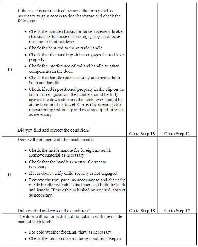
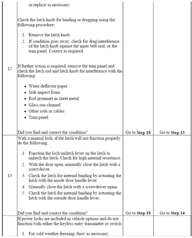
.jpg)
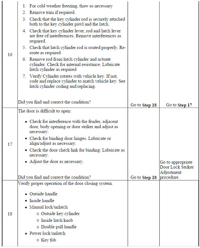
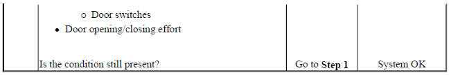
READ NEXT:
 Vehicle access - Repair instructions
FRONT SIDE DOOR INSIDE HANDLE CABLE REPLACEMENT
Fig. 9: Rear Side Door Inside Handle Cable And Cover
Front Side Door Inside Handle Cable Replacement
REAR SIDE DOOR INSIDE HANDLE CABLE REPLACEMENT
Vehicle access - Description and operation
Door ajar indicator description and operation
Door Ajar Indicator System Components
The door ajar indicator system consists of the following components:
Body control module
Instrument cluster
Driv
SEE MORE:
Automatic Transmission Shift Lock Control Function Check
Warning
When you are doing this
inspection, the vehicle could
move suddenly. If the vehicle
moves, you or others could be
injured.
Before starting this check, be
sure there is enough room
around the vehicle. It should be
parked on a level surface.
Apply the parking brake. Be
ready to ap
Supplemental Inflatable Restraints - Description and operation
SUPPLEMENTAL INFLATABLE RESTRAINT SYSTEM DESCRIPTION AND OPERATION
SIR System Overview
The supplemental inflatable restraint (SIR) system supplements the protection
offered by the seat belts. The SIR
system contains an inflatable restraint sensing and diagnostic module (SDM), air
bags, seat belt p
