Buick Encore: Vehicle Access
SCHEMATIC WIRING DIAGRAMS
SPECIFICATIONS
Fastener Tightening Specifications
.jpg)
SCHEMATIC WIRING DIAGRAMS
DOOR LOCK/INDICATOR WIRING SCHEMATICS (ENCORE)
Switches and Ajar Indicator
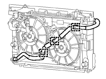
Fig. 1: Switches and Ajar Indicator
Actuators
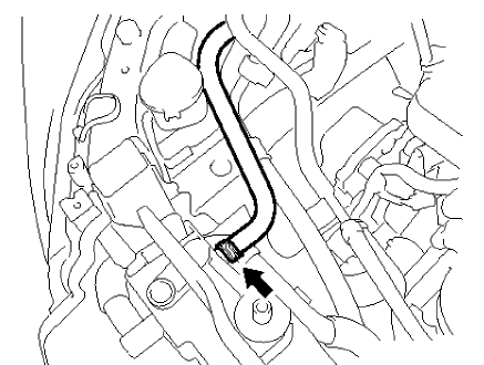
Fig. 2: Actuators
DOOR LOCK/INDICATOR WIRING SCHEMATICS (Encore)
Front Door Switches, Ajar Indicators and Rear Door Switches (-NGC)
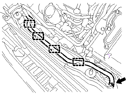
Fig. 3: Front Door Switches, Ajar Indicators and Rear Door Switches (Except
NGC)
Rear Door Switches and Child Lock Indicator (NCG)
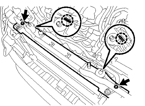
Fig. 4: Rear Door Switches and Child Lock Indicator (NCG)
Acuators and Child Lock (NCG)
Fig. 5: Acuators and Child Lock (NCG)
Actuators (Except NGC)
Fig. 6: Actuators (Except NGC)
RELEASE SYSTEMS WIRING SCHEMATICS (ENCORE)
Liftgate Release
Fig. 7: Liftgate Release
RELEASE SYSTEMS WIRING SCHEMATICS (Encore)
Liftgate Release
.gif)
Fig. 8: Liftgate Release
READ NEXT:
DTC B252C: Child security lock switch circuit
DIAGNOSTIC CODE INDEX
Diagnostic Instructions
Perform the Diagnostic System Check - Vehicle prior to using this
diagnostic procedure.
Review Strate
FRONT SIDE DOOR INSIDE HANDLE CABLE REPLACEMENT
Fig. 9: Rear Side Door Inside Handle Cable And Cover
Front Side Door Inside Handle Cable Replacement
REAR SIDE DOOR INSIDE HANDLE CABLE REPLACEMENT
Door ajar indicator description and operation
Door Ajar Indicator System Components
The door ajar indicator system consists of the following components:
Body control module
Instrument cluster
Driv
SEE MORE:
REAR SUSPENSION DESCRIPTION AND OPERATION
This vehicle has a beam rear suspension system consisting of the following
components:
An axle with integral trailing arms
A cross beam
Two coil springs
Two standard shock absorbers
Axle Assembly
The axle assembly attaches to the underbody through a r
SHIFT LOCK CONTROL WIRING SCHEMATICS (ENCORE)
Shift Lock Control System
Fig. 1: Shift Lock Control System
SHIFT LOCK CONTROL WIRING SCHEMATICS (Encore)
Shift Lock Control System
Fig. 2: Shift Lock Control System
DIAGNOSTIC INFORMATION AND PROCEDURES
DIAGNOSTIC CODE INDEX
DIAGNOSTIC CODE INDEX
.jpg)


.gif)

