Buick Encore: Fixed and Moveable Windows - Repair instructions
Windshield replacement
Special Tools
- BO-24402-A Glass Sealant Remover (Cold Knife)
- BO-39032 Stationary Glass Removal Tool
- Use an adhesive that is approved by GM
For equivalent regional tools, refer to Special Tools.
Removal Procedure
- Open the hood.
- Remove the windshield wiper arms. Refer to Windshield Wiper Arm Replacement .
- Remove the air inlet grille. Refer to Air Inlet Grille Panel Replacement (Encore) , Air Inlet Grille Panel Replacement (Encore) .
- Remove the outside moisture sensor. Refer to Windshield Outside Moisture Sensor Replacement .
- Remove the remote control door lock receiver. Refer to Remote Control Door Lock Receiver Replacement (Without UFL and LDW) , Remote Control Door Lock Receiver Replacement (With UFL and LDW) .
- Remove the inside rearview mirror. Refer to Inside Rearview Mirror Replacement .
- Remove the windshield garnish molding. Refer to Windshield Garnish Molding Replacement (Encore) , Windshield Garnish Molding Replacement (Encore) .
WARNING: If broken glass falls into the defroster outlets, it can be blown into the passenger compartment and cause personal injury.
- Cover to protect the following parts from broken glass:
- Upper dash pad
- Defroster outlets and A/C outlets
- Seats and carpeting
WARNING: Refer to Glass and Sheet Metal Handling Warning
NOTE: Before cutting out a stationary window, apply a double layer of masking tape around the perimeter of the painted surfaces and the interior trim.
- Using the appropriate tool, carefully cut the windshield reveal molding in order to access the autoadhesive bead.
.gif)
Fig. 8: Separating Urethane Adhesive From Window
NOTE: Keep the cutting edge of the appropriate tool against the window. There are window locating pins, one in each upper corner of the window. Use care Not to remove or cut them off when removing the window. If the window locator pins are cut, it will be necessary to tape the window in place.
- This will allow the auto-adhesive to be separated from the window.
- Leave a base of auto-adhesive on the pinchweld flange.
- The only suitable lubrication is clean water, no oils, lubes or soaps.
- Use BO-24402-A Glass Sealant Remover (Cold Knife).
- BO-39032 Stationary Glass Removal Tool , or equivalent in order to remove the window.
.gif)
Fig. 9: Separating Bottom Of Window
- Use the appropraite tool to remove the bottom of the window from the auto-adhesive. Keep the cutting edge of the tool against the window. Do this from inside the vehicle.
.gif)
Fig. 10: Window And Retainers
- With an assistant, remove the window (2) from the vehicle. Check that the retainers (1) are still attached to the window before installing.
Installation Procedure
- Install the windshield into the opening. Refer to Adhesive Installation of Windshields.
- Remove the outside moisture sensor. Refer to Windshield Outside Moisture Sensor Replacement .
- Remove the remote control door lock receiver. Refer to Remote Control Door Lock Receiver Replacement (Without UFL and LDW) , Remote Control Door Lock Receiver Replacement (With UFL and LDW) .
- Install the rearview mirror. Refer to Inside Rearview Mirror Replacement .
- Install the windshield garnish molding. Refer to Windshield Garnish Molding Replacement (Encore) , Windshield Garnish Molding Replacement (Encore) .
- Install the air inlet grille. Refer to Air Inlet Grille Panel Replacement (Encore) , Air Inlet Grille Panel Replacement (Encore) .
- Install the windshield wipers arms. Refer to Windshield Wiper Arm Replacement .
- Remove the double layer of masking tape around the perimeter of the painted surfaces and the interior trim.
- Close the hood.
FRONT SIDE DOOR WINDOW REPLACEMENT
.gif)
Fig. 11: Front Side Door Window Rear Guide
Front Side Door Window Replacement
.jpg)
REAR SIDE DOOR WINDOW REPLACEMENT
.gif)
Fig. 12: Rear Side Door Window
Rear Side Door Window Replacement
.jpg)
.jpg)
REAR SIDE DOOR STATIONARY WINDOW REPLACEMENT
.gif)
Fig. 13: Rear Side Door Stationary Window
Rear Side Door Stationary Window Replacement
.jpg)
Liftgate window replacement
Special Tools
- J 24402-A Glass Sealant (Cold Knife) Remover
- J 39032 Stationary Glass Removal Tool
- Use a urethane adhesive systems which meet GM Specification GMW 15672
Removal Procedure
WARNING: Refer to Cracked Window Warning
NOTE: Before cutting out a stationary window, apply a double layer of masking tape around the perimeter of the painted surfaces and the interior trim.
- Open the liftgate.
- Remove the liftgate trim. Refer to Liftgate Lower Trim Finish Panel Replacement .
- Disconnect the electrical connectors from the liftgate window defogger bus bar.
- Remove the rear window wiper arm. Refer to Rear Window Wiper Arm Replacement .
- Remove the rear spoiler. Refer to Rear End Spoiler Replacement .
WARNING: Refer to Defroster Outlet Warning .
- Cover the following parts to protect from broken glass, seats and carpeting.
.gif)
Fig. 14: Separating Urethane Adhesive From Window
WARNING: Refer to Glass and Sheet Metal Handling Warning .
NOTE: Keep the cutting edge of the tool against the window.
- Remove the window from the urethane adhesive.
- Leave a base of urethane approximately 2 mm (0.078 in) on the pinch-weld flange.
- The only suitable lubrication is clear water, no oils, lubes or soaps.
- Use J 24402-A glass sealant (cold knife) remover , J 39032 stationary glass removal tool or equivalent in order to remove the window.
NOTE: Keep the cutting edge of the knife/tool against the window. Do this from inside the vehicle.
- If necessary, use a long utility knife or similar tool to remove the bottom corners of the window from the urethane adhesive.
.gif)
Fig. 15: Rear Window
- With an assistant, remove the window (2) from the vehicle. Check that the retainers (1) are still attached to the window before installing
Installation Procedure
- Install the liftgate window into the opening. Refer to Adhesive Installation of Liftgate Windows.
- Install the rear spoiler. Refer to Rear End Spoiler Replacement .
- Install the rear window wiper arm. Refer to Rear Window Wiper Arm Replacement .
- Connect the liftgate window defogger electrical connectors to the bus bar.
- Install the liftgate trim. Refer to Liftgate Lower Trim Finish Panel Replacement .
- Remove the double layer of masking tape around the perimeter of the painted surfaces and the interior trim.
- Close the liftgate.
FRONT SIDE DOOR STATIONARY WINDOW REPLACEMENT
.gif)
Fig. 16: Front Side Door Stationary Window
Front Side Door Stationary Window Replacement
.jpg)
.jpg)
FRONT SIDE DOOR WINDOW SWITCH REPLACEMENT (DRIVER SIDE, ENCORE)
.gif)
Fig. 17: Front Side Door Window Switch (Driver Side)
Front Side Door Window Switch Replacement (Driver Side, Encore)
.jpg)
FRONT SIDE DOOR WINDOW SWITCH REPLACEMENT (PASSENGER SIDE, ENCORE)
.gif)
Fig. 18: Front Side Door Window Switch (Passenger Side)
Front Side Door Window Switch Replacement (Passenger Side, Encore)
.jpg)
.jpg)
FRONT SIDE DOOR WINDOW SWITCH REPLACEMENT (DRIVER SIDE, Encore)
.gif)
Fig. 19: Front Side Door Window Switch (Driver Side)
Front Side Door Window Switch Replacement (Driver Side, Encore)
.jpg)
FRONT SIDE DOOR WINDOW SWITCH REPLACEMENT (PASSENGER SIDE, Encore)
.gif)
Fig. 20: Front Side Door Window Switch (Passenger Side)
Front Side Door Window Switch Replacement (Passenger Side, Encore)
.jpg)
REAR SIDE DOOR WINDOW SWITCH REPLACEMENT
.gif)
Fig. 21: Rear Side Door Window Switch
Rear Side Door Window Switch Replacement
.jpg)
FRONT SIDE DOOR WINDOW REGULATOR REPLACEMENT (POWER)
.gif)
Fig. 22: Front Side Door Window Regulator (Power)
Front Side Door Window Regulator Replacement (Power)
.jpg)
.jpg)
FRONT SIDE DOOR WINDOW REGULATOR REPLACEMENT (MANUAL)
.gif)
Fig. 23: Front Side Door Window Regulator (Manual)
Front Side Door Window Regulator Replacement (Manual)
.jpg)
.jpg)
Window motor programming - express function
Window Motor Normalized Procedure
A window motor that has not been normalized will no longer perform the express up and express down functions, this may occur during the following conditions:
- When a window motor has been disconnected or replaced
- When a door harness has been disconnected
- When the battery has been disconnected or replaced
NOTE:
When DTC B3205 4B & 3210 4B are set, the following warnings will be displayed on the driver information center:
Open, then Close Driver Window
Open, then Close Passenger Window
These warnings will clear once the windows have been "Normalized" and the respective DTC will clear.
To normalize the window motor, follow these steps:
NOTE:
The doors must be completely closed prior to normalizing the windows, a door that is open or ajar may cause the power window to function abnormally or to become inoperative while performing the normalizing procedure. If this occurs, verify that the door is completely closed then repeat the normalizing procedure.
NOTE:
For vehicles equipped with a folding convertible top, the top must be closed and firmly latched prior to normalizing the windows.
- Ignition ON.
- Starting with the window completely UP, press and hold the power window switch until the window is fully open and continue holding the switch down for approximately 5 seconds after the window is completely open.
- Pull the power window switch up until the window is fully closed and continue holding the switch up for approximately 5 seconds after the window is completely closed.
The window should now be normalized and the window should perform the express up and express down functions.
Window Motor Relearn Procedure
A relearn procedure may need to be performed for any Local Interconnect Network (LIN) window motor for the following conditions:
- When the window glass is out of alignment
- When the window glass has been replaced
- When the door has been replaced
- When the window regulator has been replaced
NOTE:
Prior to performing the relearn procedure the vehicle must have all 4 wheels properly inflated and mounted, the vehicle must be sitting on a level surface and all doors must be completely closed and for vehicles equipped with a folding convertible top, the top must be closed and firmly latched..
To relearn the window motor, follow these steps:
- Ignition ON.
- With a scan tool, select Module Diagnosis, Body Control Module, Configuration/Reset Functions and then select the appropriate Clear Window Learn Values for the window motor requiring the relearn procedure.
- After the learn procedure, exit the scan tool learn procedure completely, the power window cannot be normalized and will not function until you exit the program.
- Starting with the window completely UP, press and hold the power window switch until the window is fully open and continue holding the switch down for approximately 5 seconds after the window is completely open.
- Pull the power window switch up until the window is fully closed and continue holding the switch up for approximately 5 seconds after the window is completely closed.
The window is now reprogrammed.
FRONT SIDE DOOR WINDOW REGULATOR MOTOR REPLACEMENT
.gif)
Fig. 24: Front Side Door Window Regulator Motor
Front Side Door Window Regulator Motor Replacement
.jpg)
.jpg)
REAR SIDE DOOR WINDOW REGULATOR REPLACEMENT (POWER)
.gif)
Fig. 25: Rear Side Door Window Regulator (Power)
Rear Side Door Window Regulator Replacement (Power)
.jpg)
.jpg)
REAR SIDE DOOR WINDOW REGULATOR REPLACEMENT
.gif)
Fig. 26: Rear Side Door Window Regulator
Rear Side Door Window Regulator Replacement
.jpg)
.jpg)
REAR SIDE DOOR WINDOW REGULATOR MOTOR REPLACEMENT
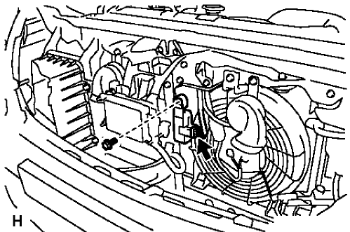
Fig. 27: Rear Side Door Window Regulator Motor
Rear Side Door Window Regulator Motor Replacement
.jpg)
.jpg)
FRONT SIDE DOOR WINDOW REGULATOR HANDLE REPLACEMENT
.gif)
Fig. 28: Front Side Door Window Regulator Handle
Front Side Door Window Regulator Handle Replacement
.jpg)
.gif)
FRONT SIDE DOOR WINDOW REAR GUIDE REPLACEMENT
.gif)
Fig. 29: Front Side Door Window Rear Guide
Front Side Door Window Rear Guide Replacement
.jpg)
.jpg)
REAR SIDE DOOR WINDOW REAR GUIDE REPLACEMENT
.gif)
Fig. 30: Rear Side Door Window Rear Guide
Rear Side Door Window Rear Guide Replacement
.jpg)
.jpg)
FRONT SIDE DOOR WINDOW OUTER SEALING STRIP REPLACEMENT
.gif)
Fig. 31: Front Side Door Window Outer Sealing Strip
Front Side Door Window Outer Sealing Strip Replacement
.jpg)
FRONT SIDE DOOR WINDOW INNER SEALING STRIP REPLACEMENT (ENCORE)
.gif)
Fig. 32: Front Side Door Window Inner Sealing Strip
Front Side Door Window Inner Sealing Strip Replacement (Encore)
.jpg)
FRONT SIDE DOOR WINDOW INNER SEALING STRIP REPLACEMENT (Encore)
.gif)
Fig. 33: Front Side Door Window Inner Sealing Strip
Front Side Door Window Inner Sealing Strip Replacement (Encore)
.jpg)
REAR SIDE DOOR WINDOW INNER SEALING STRIP REPLACEMENT
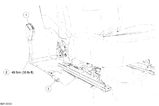
Fig. 34: Rear Side Door Window Inner Sealing Strip
Rear Side Door Window Inner Sealing Strip Replacement
.jpg)
.jpg)
REAR SIDE DOOR WINDOW OUTER SEALING STRIP REPLACEMENT
.gif)
Fig. 35: Rear Side Door Window Outer Sealing Strip
Rear Side Door Window Outer Sealing Strip Replacement
.jpg)
FRONT SIDE DOOR WINDOW WEATHERSTRIP REPLACEMENT
.gif)
Fig. 36: Front Side Door Window Weatherstrip
Front Side Door Window Weatherstrip Replacement
.jpg)
.jpg)
REAR SIDE DOOR WINDOW WEATHERSTRIP REPLACEMENT
.gif)
Fig. 37: Rear Side Door Window Weatherstrip
Rear Side Door Window Weatherstrip Replacement
.jpg)
.jpg)
Adhesive installation of windshields
WARNING: Refer to Glass and Sheet Metal Handling Warning .
- Use a urethane adhesive systems which meet GM Specification GMW 15672.
- Remove all mounds or loose pieces of urethane adhesive from the pinchweld area.
- If the original window is being reused, remove all but approximately 2 mm (3/64 in) of the existing bead of urethane adhesive from the pinchweld flange by using a clean utility knife or razor blade scraper.
- Inspect for any of the following problems in order to help prevent future breakage of the window:
- The flange of the window opening
- High weld
- Solder spots
- Hardened sealer
- Any other obstruction or irregularity in the pinchweld flange
NOTE: If corrosion of the pinch-weld flange is present or if sheet metal repairs or replacements are required, the pinch-weld flange must be refinished in order to restore the bonding area strength. If paint repairs are required, mask the flange bonding area prior to applying the color coat in order to provide a clean primer only surface. Materials such as BASF DE15, DuPont 2610, Sherwin-Williams PSE 4600 and NP70 and Martin-Semour 5120 and 5130 PPG DP90LF SPIES/ HECKER 3688/8590 - 3688/5150 -4070/5090 STANDOX 11158/13320 - 14653/14980 products are approved for this application.
- After repairing the opening as indicated, perform the following steps:
- Remove all traces of broken glass from the outer cowl panel, seats, floor and defroster ducts.
- Clean around the edge of the inside surface of the window with a 50/50 mixture of isopropyl alcohol and water by volume on a dampened lint free cloth.
- Verify all primers and urethane adhesive are within expiration dates.
.gif)
Fig. 38: Applying Pinch-Weld Primer
WARNING: Failure to prep the area prior to the application of primer may cause insufficient bonding of urethane adhesive. Insufficient bonding of urethane adhesive may allow unrestrained occupants to be ejected from the vehicle resulting in personal injury.
- Apply the primer to the surface of the pinch-weld flange (1).
- Allow the pinch-weld primer to dry per auto-adhesive instructions by the manufacturer's.
- With an assistant, dry fit the window (2) to the opening in order to determine the correct position.
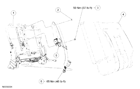
Fig. 39: Aligning Tape Lines On Window To Body
- Use masking tape in order to mark the locations (1) of the window (2) in the opening.
- Cut the masking tape in the center and remove the window from the opening.
.jpg)
Fig. 40: Applying Glass Prep
- Apply glass prep clear to the area approximately 10-16 mm (3/8-5/8 in) around the entire perimeter of the window inner surface.
Immediately wipe the glass primed area using a clean, lint-free cloth.
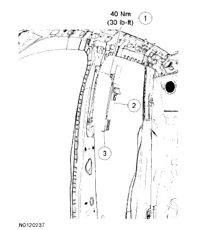
Fig. 41: Applying Glass Prep
- Apply bonded-glass primer and let dry per auto-adhesive instructions by the manufacturer's.
.gif)
Fig. 42: Applying Glass Primer
- Apply the auto-adhesive primer-application (2) around the perimeter of the window (1) per auto-adhesive instructions by the manufacturer's.
- Apply the glass primer black to the same areas that glass prep clear was applied.
- Allow the glass primer to dry per auto-adhesive instructions by the manufacturer's.
.gif)
Fig. 43: View Of Modified Applicator Nozzle
- Use a cartridge-type caulking gun in order to apply a smooth, continuous bead.
Cut the applicator nozzle to provided a V cut to apply the auto-adhesive.
.gif)
Fig. 44: Applying Urethane Adhesive To Inner Surface Of Window
- Use the edge of the window as a guide for the nozzle in order to apply the urethane adhesive (1) to the inner surface of the window (3).
.gif)
Fig. 45: Window And Retainers
NOTE: If the locating pins were cut off it will be necessary to tape the window in place until the auto-adhesive cures per auto-adhesive instructions by the manufacturer's.
- With an assistant, align the window locating pins (1) to the slots located in each corner of the pinch-weld flange. Lower the window (2) to touch the auto-adhesive.
Fig. 46: Pressing Window Into Place
- Gently depress the window on the auto-adhesive bead until the window reveal molding is seated.
- Tape the window to the body in order to minimize movement and until the auto-adhesive cures per autoadhesive instructions by the manufacturer's.
.jpg)
Fig. 47: Cleaning Excess Urethane Adhesive From Body
- Ensure all excess urethane adhesive is cleaned from the body before water test.
.gif)
Fig. 48: Performing Water Hose Test
NOTE: Do not direct a hard stream of high pressure water to the freshly applied urethane adhesive.
- Use a soft spray of warm water in order to immediately water test the window.
- Inspect the window for leaks.
- If any leaks are found, use a plastic paddle in order to apply extra urethane adhesive at the leak point.
- Retest the window for leaks.
WARNING: Insufficient curing of urethane adhesive may allow unrestrained occupants to be ejected from the vehicle resulting in personal injury.
- For the moisture-curing type of urethane adhesive, allow a minimum of 6 hours at 21ºC (70ºF) or greater and with at least 30 percent relative humidity. Allow at least 24 hours for the complete curing of the urethane adhesive.
- For the chemical-curing type of urethane adhesive, allow a minimum of 1 hour .
Do NOT physically disturb the repair area until after these minimum times have elapsed.
- Maintain the following conditions in order to properly cure the urethane adhesive:
- Partially lower a door window in order to prevent pressure buildups when closing doors before the urethane adhesive cures.
- Do not drive the vehicle until the urethane adhesive is cured. Refer to the above curing times.
- Do not use compressed air in order to dry the urethane adhesive.
- Complete the window installation.
Adhesive installation of liftgate windows
WARNING: Refer to Glass and Sheet Metal Handling Warning .
- Use a urethane adhesive systems which meet GM Specification GMW 15672.
- Remove all mounds or loose pieces of urethane adhesive from the pinchweld area.
- If the original window is being reused, remove all but approximately 2 mm (3/64 in) of the existing bead of urethane adhesive from the pinchweld flange by using a clean utility knife or razor blade scraper.
- Inspect for any of the following problems in order to help prevent future breakage of the window:
- The flange of the window opening
- High weld
- Solder spots
- Hardened sealer
- Any other obstruction or irregularity in the pinchweld flange
NOTE: If corrosion of the pinch-weld flange is present or if sheet metal repairs or replacements are required, the pinch-weld flange must be refinished in order to restore the bonding area strength. If paint repairs are required, mask the flange bonding area prior to applying the color coat in order to provide a clean primer only surface. Materials such as BASF DE15, DuPont 2610, Sherwin-Williams PSE 4600 and NP70 and Martin-Semour 5120 and 5130 PPG DP90LF SPIES/ HECKER 3688/8590 - 3688/5150 - 4070/5090 STANDOX 11158/13320 - 14653/14980 products are approved for this application.
- After repairing the opening as indicated, perform the following steps:
- Remove all traces of broken glass from the outer cowl panel, seats, floor and defroster ducts.
- Clean around the edge of the inside surface of the window with a 50/50 mixture of isopropyl alcohol and water by volume on a dampened lint free cloth.
- Verify all primers and urethane adhesive are within expiration dates.
.gif)
Fig. 49: Applying Pinch-Weld Primer
WARNING: Failure to prep the area prior to the application of primer may cause insufficient bonding of urethane adhesive. Insufficient bonding of urethane adhesive may allow unrestrained occupants to be ejected from the vehicle resulting in personal injury.
- Apply the primer to the surface of the pinch-weld flange (1).
- Allow the pinch-weld primer to dry per auto-adhesive instructions by the manufacturer's.
- With an assistant, dry fit the window (2) to the opening in order to determine the correct position.
Fig. 50: Aligning Tape Lines On Window To Body
- Use masking tape in order to mark the locations (1) of the window (2) in the opening.
- Cut the masking tape in the center and remove the window from the opening.
Fig. 51: Applying Glass Prep
- Apply glass prep clear to the area approximately 10-16 mm (3/8-5/8 in) around the entire perimeter of the window inner surface.
Immediately wipe the glass primed area using a clean, lint-free cloth.
.gif)
Fig. 52: Applying Glass Prep
- Apply bonded-glass primer and let dry per auto-adhesive instructions by the manufacturer's.
.gif)
Fig. 53: Applying Glass Primer
- Apply the auto-adhesive primer-application (2) around the perimeter of the window (1) per auto-adhesive instructions by the manufacturer's.
- Apply the glass primer black to the same areas that glass prep clear was applied.
- Allow the glass primer to dry per auto-adhesive instructions by the manufacturer's.
.jpg)
Fig. 54: View Of Modified Applicator Nozzle
- Use a cartridge-type caulking gun in order to apply a smooth, continuous bead.
Cut the applicator nozzle to provided a V cut to apply the auto-adhesive.
- Install the window reveal molding, if equipped.
.jpg)
Fig. 55: Applying Urethane Adhesive To Inner Surface Of Window
- Use the edge of the window as a guide for the nozzle in order to apply the urethane adhesive (1) to the inner surface of the window (3).
.gif)
|
Fig. 56: Rear Window
NOTE: If the locating pins were cut off it will be necessary to tape the window in place until the auto-adhesive cures per auto-adhesive instructions by the manufacturer's.
- With an assistant, align the window locating pins (1) to the slots located in each corner of the pinch-weld flange. Lower the window (2) to touch the auto-adhesive.
.jpg)
Fig. 57: Aligning Tape Lines On Window To Body
- If the locating pins were damaged, align the masking tape (1) lines on the window (2) and the body.
.jpg)
Fig. 58: Pressing Window Into Place
- Gently depress the window on the auto-adhesive bead until the window reveal molding is seated.
- Tape the window to the body in order to minimize movement and until the auto-adhesive cures per autoadhesive instructions by the manufacturer's.
.gif)
Fig. 59: Cleaning Excess Urethane Adhesive From Body
- Ensure all excess urethane adhesive is cleaned from the body before water test.
.jpg)
Fig. 60: Performing Water Hose Test
NOTE: Do not direct a hard stream of high pressure water to the freshly applied urethane adhesive.
- Use a soft spray of warm water in order to immediately water test the window.
- Inspect the window for leaks.
- If any leaks are found, use a plastic paddle in order to apply extra urethane adhesive at the leak point.
- Retest the window for leaks.
WARNING: Insufficient curing of urethane adhesive may allow unrestrained occupants to be ejected from the vehicle resulting in personal injury.
- For the moisture-curing type of urethane adhesive, allow a minimum of 6 hours at 21ºC (70ºF) or greater and with at least 30 percent relative humidity. Allow at least 24 hours for the complete curing of the urethane adhesive.
- For the chemical-curing type of urethane adhesive, allow a minimum of 1 hour .
Do NOT physically disturb the repair area until after these minimum times have elapsed.
- Maintain the following conditions in order to properly cure the urethane adhesive:
- Partially lower a door window in order to prevent pressure buildups when closing doors before the urethane adhesive cures.
- Do not drive the vehicle until the urethane adhesive is cured. Refer to the above curing times.
- Do not use compressed air in order to dry the urethane adhesive.
- Complete the window installation.

