Buick Encore: Schematic wiring diagrams
Automatic transmission controls wiring schematics (ENCORE, MH8 OR MHB)
Module Power, Ground, Data Communication, and MIL
.jpg)
Fig. 1: Module Power, Ground, Data Communication, and MIL
Speed and Temperature Sensors, Pressure and Shift Controls
.jpg)
Fig. 2: Speed and Temperature Sensors, Pressure and Shift Controls
Internal Mode Switch and Tap Up/Tap Down Switches
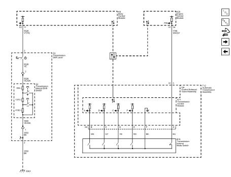
Fig. 3: Internal Mode Switch and Tap Up/Tap Down Switches
Shift Indicator
.jpg)
Fig. 4: Shift Indicator
AUTOMATIC TRANSMISSION CONTROLS SCHEMATICS (Encore, MH8 OR MHB)
Module Power, Ground, Data Communication, and MIL
.jpg)
Fig. 5: Module Power, Ground, Data Communication, and MIL
Speed and Tempreature Sensors, Pressure and Shift Controls
.jpg)
Fig. 6: Speed and Tempreature Sensors, Pressure and Shift Controls
Internal Mode Switch and Tap Up/Tap Down Switches
.jpg)
Fig. 7: Internal Mode Switch and Tap Up/Tap Down Switches
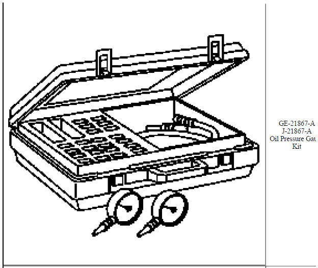
Special tools and equipment
SPECIAL TOOLS
.jpg)
.jpg)
.jpg)
.jpg)
.jpg)
.jpg)
.jpg)
.jpg)
.jpg)
.jpg)
.jpg)
.jpg)
.jpg)
.jpg)
.jpg)
.jpg)
.jpg)
.jpg)
.jpg)
.jpg)
.jpg)
.jpg)
.jpg)
.jpg)
.jpg)
.jpg)
.jpg)
.jpg)
.jpg)
.jpg)
.jpg)
.jpg)
.jpg)
.jpg)
.jpg)
.jpg)
.jpg)
.jpg)
.jpg)
.jpg)
.jpg)
.jpg)
.jpg)
.jpg)
.jpg)
.jpg)
.jpg)
.jpg)
.jpg)
READ NEXT:
 Description and operation
Definitions and abbreviations
Throttle Positions
Engine Braking
A condition where the engine is used to slow the vehicle by manually
downshifting during a zero throttle
coastdown.
Full Throttle Downs
Specifications
FASTENER TIGHTENING SPECIFICATIONS (ON VEHICLE)
Fastener Tightening Specifications (On Vehicle)
FASTENER TIGHTENING SPECIFICATIONS (OFF VEHICLE)
Fastener Tightening Specifications (Off Vehicle)
Manual Transmission - M20 M32 (MR5)
SPECIFICATIONS
FASTENER TIGHTENING SPECIFICATIONS
Fastener Tightening Specifications
MANUAL TRANSMISSION SPECIFICATIONS
Manual Transmission Specifications
Schematic wiring diagrams
MANUAL TRANSM
SEE MORE:
Schematic wiring diagrams
ENGINE CONTROLS WIRING SCHEMATICS (ENCORE)
Module Power, Ground, Serial Data, and MIL
Fig. 1: Module Power, Ground, Serial Data, and MIL
5V1, 5V2, and Low Reference Bus (1 of 2)
Fig. 2: 5V1, 5V2, and Low Reference Bus (1 of 2)
5V3, 5V4, and Low Reference Bus (2 of 2)
Fig. 3: 5V3, 5V4, and Low
Driver Information
Center (DIC)
The Driver Information Center (DIC)
displays information about the
vehicle. It also displays warning
messages if a system problem is
detected. See Vehicle Messages. All messages appear in the
DIC display in the center of the
instrument cluster.
The vehicle may also have features
that can be customi
