Buick Encore: Repair instructions - off vehicle
Engine support fixture
.gif)
Fig. 237: Engine Support Fixture Components
Engine Support Fixture
.jpg)
.jpg)
ENGINE MOUNT BRACKET REMOVAL
.gif)
Fig. 238: Engine Mount Bracket And Bolts
- Remove the 3 engine mount bracket bolts (1).
- Remove the engine mount bracket (2).
CAMSHAFT TIMING CHAIN INSPECTION
Special Tools
- EN-952 Fixing Pin
- EN-953-A Fixing Tool
- EN-49977-100 Transmitter Disc Fixation
For equivalent regional tools, refer to Special Tools.
- Remove the ignition coil. Refer to Ignition Coil Replacement .
- Remove the camshaft cover. Refer to Camshaft Cover Replacement
.gif)
Fig. 239: Bore And Mark
- Remove the right front wheelhouse liner. Refer to Front Wheelhouse Liner Replacement (Encore) , Front Wheelhouse Liner Replacement (Encore)
- Rotate the engine clockwise until the bore (2) in the crankshaft balancer aligns with the mark (1) on the engine front cover.
.gif)
Fig. 240: Camshaft Grooves
- Examine that the camshaft grooves (1) are visible as shown. If the camshaft grooves are not visible rotate the crankshaft 360º.
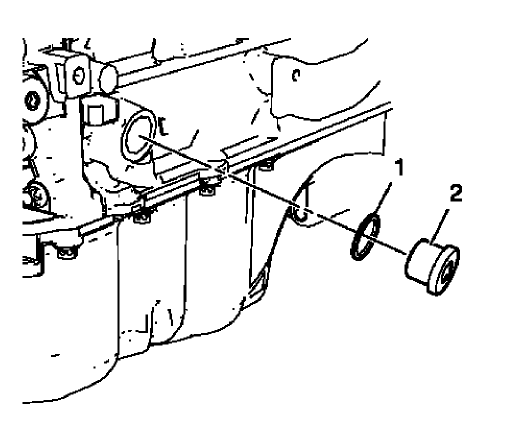
Fig. 241: Crankshaft Bearing Cap Tie Plate Hole Plug And Seal Ring
- Remove the crankshaft bearing cap tie plate hole plug (2) and the seal ring (1).
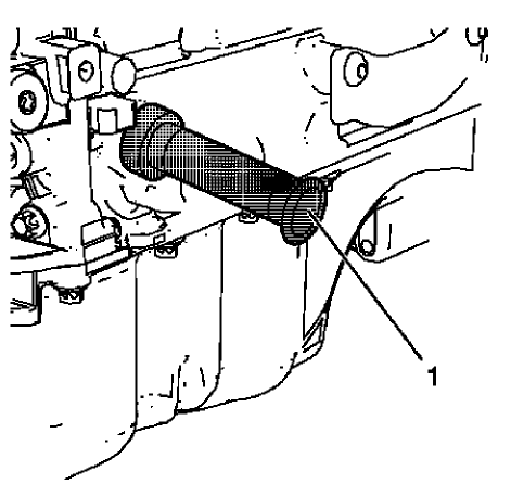
Fig. 242: Fixing Pin
CAUTION: To ensure proper crankshaft top dead center (TDC) alignment, the retention pin should fit easily through the bore in the crankshaft tie plate and into the crankshaft. Binding of the retention pin could affect proper engine timing.
- Install EN-952 fixing pin (1) to hold the crankshaft in TDC position.
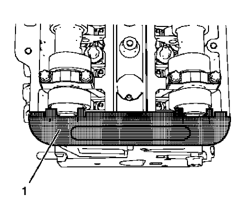
Fig. 243: Fixing Tool
NOTE: The fixing tool should be installed completely to both camshaft grooves without high effort.
- Install EN-953-A fixing tool (1) to the camshafts.
.gif)
Fig. 244: Transmitter Disc Fixation Tool And Bolts
NOTE: A wrong installation position is possible. Make sure that the fixation tool is installed without clearance to the cylinder head in areas (3) and (4).
- Install EN-49977-100 transmitter disc fixation (1) to inspect the correct position of the camshaft position exciter wheels.
- Tighten the bolts (2) of EN-49977-100 transmitter disc fixation.
- If EN-953-A fixing tool or EN-49977-100 transmitter disc fixation can not be installed, refer to Camshaft Timing Chain Adjustment.
- Remove EN-49977-100 transmitter disc fixation.
- Remove EN-953-A fixing tool.
- Remove EN-952 fixing pin.
CAUTION: Refer to Fastener Caution
- Install crankshaft bearing cap tie plate hole plug and seal ring and tighten to 40 N.m (30 lb ft).
- Install the right front wheelhouse liner. Refer to Front Wheelhouse Liner Replacement (Encore) , Front Wheelhouse Liner Replacement (Encore)
- Install the camshaft cover. Refer to Camshaft Cover Installation.
- Install the ignition coil. Refer to Ignition Coil Installation
Camshaft timing chain adjustment
Special Tools
- EN-952 Fixing Pin
- EN-953-A Fixing Tool
- EN-49977-100 Fixation Sensor Discs
For equivalent regional tools, refer to Special Tools.
- Remove the ignition coil. Refer to Ignition Coil Replacement .
- Remove the camshaft cover. Refer to Camshaft Cover Replacement.
- Remove the camshaft position actuator solenoid valves. Refer to Camshaft Position Actuator Solenoid Valve Replacement .
- Remove the right front wheelhouse liner. Refer to Front Wheelhouse Liner Replacement (Encore) , Front Wheelhouse Liner Replacement (Encore) .
.gif)
Fig. 245: Bore And Mark
- Rotate the engine clockwise until the bore (2) in the crankshaft balancer aligns with the mark (1) on the engine front cover.
.gif)
Fig. 246: Crankshaft Bearing Cap Tie Plate Hole Plug And Seal Ring
- Remove the crankshaft bearing cap tie plate hole plug (2) and the seal ring (1).
.gif)
Fig. 247: Fixing Pin
CAUTION: To ensure proper crankshaft top dead center (TDC) alignment, the retention pin should fit easily through the bore in the crankshaft tie plate and into the crankshaft. Binding of the retention pin could affect proper engine timing.
- Install the EN-952 fixing pin (1) to hold the crankshaft in TDC position.
.gif)
Fig. 248: Intake Camshaft Sprocket Bolt And Wrench
- Loosen the intake camshaft sprocket bolt (2) while holding the hexagon of the intake camshaft with a wrench (1) until the camshaft position exciter wheel is clearly rotatable.
- Loosen the exhaust camshaft sprocket bolt while holding the hexagon of the exhaust camshaft with a wrench until the camshaft position exciter wheel is clearly rotatable.
.gif)
Fig. 249: Fixing Tool
NOTE: The fixing tool should be installed completely to both camshaft grooves without high effort.
- Adjust the camshafts so that the EN-953-A fixing tool (1) can be installed.
.gif)
Fig. 250: Upper Timing Chain Guide And Bolts
- Remove the 2 upper timing chain guide bolts (1).
- Remove the upper timing chain guide (2).
.gif)
Fig. 251: Intake Camshaft Sprocket Gearing And Special Tool
NOTE: Push the fixing tool in the direction of the arrow to ensure it engages without clearance.
- Install the EN-49977-200 fixing tool (2) and adjust the gearing of the fixing tool so it engages with the intake camshaft sprocket gearing (1).
.gif)
Fig. 252: Adjuster Bolt And Fastening Bolts
- Tighten the 2 fastening bolts (1) of the EN-49977-200 fixing tool while pushing the fixing tool in direction of the arrow.
- Tighten the adjuster bolt (2).
.gif)
Fig. 253: Fastening Bolts And Fixation Tool
NOTE: A wrong installation position is possible. Make sure that the fixation tool is installed without clearance to the cylinder head in areas (3) and (5).
- Install the EN-49977-100 fixation (2) to find and hold the camshaft position exciter wheels in the correct position.
- Tighten the 2 fastening bolts (6) of the EN-49977-100 fixation.
CAUTION: Refer to Fastener Caution .
- Tighten the intake camshaft sprocket bolt (4) while holding the hexagon (1) of the intake camshaft to 50 N.m (37 lb ft).
- Tighten the intake camshaft sprocket bolt (4) while holding the hexagon (1) of the intake camshaft an additional 60º.
- Tighten the exhaust camshaft sprocket bolt while holding the hexagon of the exhaust camshaft to 50 N.m (37 lb ft).
- Tighten the exhaust camshaft sprocket bolt while holding the hexagon of the exhaust camshaft an additional 60º.
- Remove the EN-49977-100 fixation and the EN-49977-200 fixing tool.
.gif)
Fig. 254: Upper Timing Chain Guide And Bolts
- Install the upper timing chain guide (2).
- Install the 2 upper timing chain guide bolts (1) and tighten to 8 N.m (71 lb in).
- Remove the EN-953-A fixing tool.
- Remove the EN-952 fixing pin.
- Rotate the crankshaft for 720º and check the engine timing again. Repeat the adjustment procedure if necessary.
- Install the crankshaft bearing cap tie plate hole plug and seal ring and tighten to 40 N.m (30 lb ft).
- Install the right front wheelhouse liner. Refer to Front Wheelhouse Liner Replacement (Encore) , Front Wheelhouse Liner Replacement (Encore)
- Install the camshaft position actuator solenoid valves. Refer to Camshaft Position Actuator Solenoid Valve Replacement .
- Install the camshaft cover. Refer to Camshaft Cover Replacement.
- Install the ignition coil. Refer to Ignition Coil Replacement .
Draining fluids and oil filter removal
.gif)
Fig. 255: Engine Oil Filter Element, Cap And Seal Ring
- Remove the engine oil filter cap (2) along with the engine oil filter cap seal ring (3) and the oil filter element (1).
- Remove the oil pan drain plug and allow the oil to drain out.
CAUTION: Refer to Fastener Caution .
- Install the oil pan drain plug and a NEW seal ring and tighten to 14 N.m (124 lb in).
- Install the engine oil filter cap along with a NEW engine oil filter cap seal ring and a NEW oil filter element.
- Tighten the engine oil filter cap to 25 N.m (18 lb ft).
.gif)
Fig. 256: Water Pump Drain Plug And Seal Ring
- Remove the water pump drain plug (1) and the water pump drain plug seal ring (2) and allow the remaining coolant to drain out.
- Install the water pump drain plug and a NEW seal ring and tighten to 15 N.m (11 lb ft).
POSITIVE CRANKCASE VENTILATION PIPE REMOVAL
.gif)
Fig. 257: Positive Crankcase Ventilation Pipe Retainer Clips And Retainer
Clamp
- Open the 2 positive crankcase ventilation pipe retainer clips (2) and (3).
NOTE: Move retainer clamp (1) in direction of the arrow.
- Remove the positive crankcase ventilation pipe from the intake manifold.
.gif)
Fig. 258: Turbocharger, Positive Crankcase Ventilation Pipe Assembly And
Charger Air Bypass Valve Pipe
- Loosen the charger air bypass valve pipe clamp (4).
- Remove the charger air bypass valve pipe from turbocharger.
- Remove the charger air bypass valve pipe (2) from turbo charger waste regulator solenoid valve.
- Disconnect the positive crankcase ventilation pipe from turbocharger (3).
- Unclip and remove the positive crankcase ventilation pipe assembly (1) from the camshaft cover retainer clips.
EXHAUST MANIFOLD HEAT SHIELD REMOVAL
.gif)
Fig. 259: Exhaust Manifold Heat Shield
- Remove the 3 exhaust manifold heat shield bolts (1) and the washers.
- Remove the exhaust manifold heat shield (2).
WARM UP THREE-WAY CATALYTIC CONVERTER REMOVAL
.gif)
Fig. 260: Locating Catalytic Converter Components
- Disconnect the heated oxygen sensor wiring harness (3) from retainer clip.
- Remove the 2 catalytic converter to catalytic converter bracket nuts (4) and (6).
- Loosen the three way warm up catalytic converter V-clamp (1).
- Remove the three way warm up catalytic converter (5) and the catalytic converter seal (2).
Turbocharger removal
Special Tool
EN-49942 Holding Wrench
For equivalent regional tools, refer to Special Tools.
.gif)
Fig. 261: Holding Wrench And Ratchet Wrench
- Install the EN-49942 holding wrench (2) to the turbocharger coolant feed pipe. Guide a ratchet wrench (1) along with an extension through EN-49942 holding wrench to the turbocharger coolant feed pipe hollow screw.
.gif)
Fig. 262: Ratchet Wrench, Holding Wrench And Coolant Feed Pipe
NOTE: EN-49942 holding wrench (2) should be installed to turbocharger coolant feed pipe as shown. The holding wrench should be installed to avoid twist of the turbocharger coolant feed pipe during the loosening procedure.
- Loosen the turbocharger coolant feed pipe hollow screw with ratchet wrench and extension (1).
.gif)
Fig. 263: Turbocharger Oil Return Pipe
- Remove the turbocharger coolant feed pipe hollow screw (3) and the 2 seal rings (1) and (2).
- Disconnect the turbocharger oil return pipe (4) from the engine block.
.gif)
Fig. 264: Turbocharger Oil Feed Pipe Components
- Remove the turbocharger oil feed pipe bolt (5) from the oil cooler.
- Remove the turbocharger oil feed pipe hollow screw (4) and the 2 seal rings (1) and (3) and close the screw bore in the turbocharger.
- Remove the turbocharger oil feed pipe (2) and the rubber seal ring.
- Disconnect the turbocharger coolant return hose (6) from the oil cooler coolant inlet pipe and remove the turbocharger coolant return pipe bolt (7) from the oil cooler.
.gif)
Fig. 265: Turbocharger Nuts
- Remove the 8 turbocharger nuts (1).
.gif)
Fig. 266: Turbocharger Assembly And Turbocharger Gasket
- Remove the turbocharger assembly (1) and the turbocharger gasket (2).
ENGINE OIL COOLER REMOVAL
.gif)
Fig. 267: Locating Engine Oil Cooler Components
- Remove the oil cooler coolant outlet hose clamp (1).
- Remove the oil cooler coolant outlet hose (2) from engine coolant thermostat housing.
- Remove the oil cooler coolant inlet hose clamp (3).
- Remove the oil cooler coolant inlet hose (4) from water outlet.
- Remove the oil cooler coolant outlet pipe bolt (7).
- Remove the 3 oil cooler bolts (5).
- Remove the engine oil cooler assembly (6) and the 2 oil cooler sealings (8) and (9).
ENGINE COOLANT THERMOSTAT HOUSING REMOVAL
.gif)
Fig. 268: Engine Coolant Thermostat Housing
- Remove the 3 engine coolant thermostat housing bolts (1).
- Remove the engine coolant thermostat housing (2) and the engine coolant thermostat housing seal ring (3).
WATER OUTLET REMOVAL
.gif)
Fig. 269: Water Outlet, Bolts And Seal Ring
- Remove the 3 water outlet bolts (3).
- Remove the water outlet (2) and the water outlet seal ring (1).
DRIVE BELT TENSIONER REMOVAL
.gif)
Fig. 270: Drive Belt Tensioner And Bolts
CAUTION: The drive belt tensioner must always be in a pre-tensioned state and must never be free from tension. If the drive belt tensioner is free from the belt tension, it must always stay fixed with an appropriate locking pin. Failure to follow this instruction will lead to a damage of the drive belt tensioner.
- Remove the upper drive belt tensioner bolt (2).
- Remove the lower drive belt tensioner bolt (3).
- Remove the drive belt tensioner (1).
AIR CONDITIONING COMPRESSOR BRACKET REMOVAL
.gif)
Fig. 271: Power Steering Pump Bracket/Air Conditioning Compressor Bracket And
Bolts
- Remove the 3 air conditioning compressor bracket bolts (1).
- Remove the air conditioning compressor bracket (2).
WATER PUMP PULLEY REMOVAL
.gif)
Fig. 272: Water Pump Pulley
- Loosen the 3 water pump pulley bolts (2) while holding up the water pump pulley hub with a wrench.
- Remove the 3 water pump pulley bolts (2).
- Remove the water pump pulley (1).
CRANKSHAFT BALANCER REMOVAL
Special Tools
- EN-956-1 Extension
- EN-49979 Crankshaft Shock Mount Retainer
For equivalent regional tools, refer to Special Tools.
- Install EN-49979 retainer to EN-956-1 extension.
.gif)
Fig. 273: Crankshaft Balancer, Retainer And Extension
NOTE: The crankshaft balancer can be incorrectly installed 180º from the required position. Be sure to note the location of the alignment hole on the crankshaft balancer prior to removing the crankshaft balancer from the engine.
- Loosen the crankshaft balancer bolt (4) while fixing the crankshaft balancer (3) with EN-49979 retainer (1) and EN-956-1 extension (2).
.gif)
Fig. 274: Crankshaft Balancer And Bolt
- Remove and DISCARD the crankshaft balancer bolt (2).
- Remove the crankshaft balancer (1).
WATER PUMP REMOVAL
.gif)
Fig. 275: Water Pump, Gasket And Bolts
- Remove the 5 short water pump bolts (4) and the 5 long water pump bolts (3).
- Remove the water pump (2).
- Remove the water pump gasket (1).
THROTTLE BODY REMOVAL
.gif)
Fig. 276: Throttle Body And Bolts
- Remove the 4 throttle body bolts (3).
- Remove the throttle body (2) and the throttle body seal ring (1).
INTAKE MANIFOLD REMOVAL
.gif)
Fig. 277: Intake Manifold Bolts
NOTE: Intake manifold bolts remain in intake manifold screw bores.
- Remove the 6 intake manifold bolts (1).
.gif)
Fig. 278: Intake Manifold
- Remove the intake manifold (1) along with the intake manifold gasket.
GENERATOR REMOVAL
.gif)
Fig. 279: Generator And Bolts
- Remove the 2 generator bolts (2).
- Remove the generator (1).
STARTER REMOVAL
.gif)
Fig. 280: Starter, Bolt, Stud And Washer
- Remove the upper starter bolt (2) and if equipped the washer (1).
- Remove the lower starter bolt stud (3) and if equipped the washer.
- Remove the starter (4).
ENGINE FLYWHEEL REMOVAL
Special Tools
EN-652 Flywheel Holder
For equivalent regional tools, refer to Special Tools
.gif)
Fig. 281: Engine Flywheel And Holder
- Install EN-652 holder (1) to hold the engine flywheel (2).
.gif)
Fig. 282: Engine Flywheel And Bolts
- Remove and DISCARD the 6 engine flywheel bolts (2).
- Remove the engine flywheel (1).
IGNITION COIL REMOVAL
Special Tools
EN-6009 Remover and Installer Ignition Module
For equivalent regional tools, refer to Special Tools.
.gif)
Fig. 283: Ignition Coil Bolts
- Remove the 2 ignition coil bolts (1).
.gif)
Fig. 284: Ignition Coil And Remover/Installer
- Install EN-6009 remover and installer (2) and remove the ignition coil (1).
CAMSHAFT COVER REMOVAL
.gif)
Fig. 285: Engine Oil Level Indicator
- Remove the oil level indicator (1).
.gif)
Fig. 286: Camshaft Cover And Gasket
- Remove the 15 camshaft cover bolts (1).
- Remove the camshaft cover (2) and the camshaft cover gasket (3).
CAMSHAFT POSITION ACTUATOR SOLENOID VALVE REMOVAL
.gif)
Fig. 287: Camshaft Position Actuator Solenoid Valve Bolts
- Remove the 4 camshaft position actuator solenoid valve bolts (1).
.gif)
Fig. 288: Intake Camshaft Position Actuator Solenoid Valve And Exhaust
Camshaft Position Actuator Solenoid Valve
- Move the intake camshaft position actuator solenoid valve (1) carefully counter clockwise in the position shown.
- Move the exhaust camshaft position actuator solenoid valve (2) carefully clockwise in the position shown.
.gif)
Fig. 289: Camshaft Position Actuator Solenoid Valves And Seal Rings
CAUTION: The camshaft position actuator solenoid valves must be kept parallel to the engine front cover during removal and installation. The camshaft position actuator solenoid valves can be damaged if they become wedged or stuck during this process.
- Carefully remove the 2 camshaft position actuator solenoid valves (2) and the seal rings (1).
OIL PAN REMOVAL
.gif)
Fig. 290: Oil Pan Bolts
- Remove the 16 oil pan bolts (1).
.gif)
Fig. 291: Oil Pan Prying Area
CAUTION: Pry the oil pan carefully in order to prevent damage to the transaxle case or the oil pan sealing surfaces.
- Place a suitable prying tool to the area shown (1) and carefully pry the oil pan loose.
.gif)
Fig. 292: Oil Pan
- Remove the oil pan (1).
ENGINE FRONT COVER AND OIL PUMP REMOVAL
- Set engine to TDC. Refer to Camshaft Timing Chain Inspection.
.gif)
Fig. 293: M6, M10 Front Cover Bolts And Engine Front Cover
- Remove the 13 engine front cover bolts M6 (1).
- Remove the 2 engine front cover bolts M10 (2).
- Remove the engine front cover.
Camshaft timing chain removal
Special Tools
- EN-952 Fixing Pin
- EN-953-A Fixing Tool
- EN-955-10 Fixing Pin from EN-955 Kit
For equivalent regional tools, refer to Special Tools.
- The engine should be adjusted to TDC.
- The crankshaft should be fixed with EN-952 fixing pin.
- The camshaft should be fixed with EN-953-A fixing tool.
.gif)
Fig. 294: Timing Chain And Timing Chain Tensioner
- Push the timing chain (2) in direction to the timing chain tensioner (1) and fix the tensioner with EN-955- 10 fixing pin (3).
.gif)
Fig. 295: Upper Timing Chain Guide And Bolts
- Remove the 2 upper timing chain guide bolts (1).
- Remove the upper timing chain guide (2).
.gif)
Fig. 296: Timing Chain Guide Right Side
- Remove the 2 timing chain guide right side bolts (2).
- Remove the timing chain guide right side (1).
.gif)
Fig. 297: Timing Chain Tensioner Shoe And Bolt
- Remove the timing chain tensioner shoe bolt (2).
- Remove the timing chain tensioner shoe (1).
.gif)
Fig. 298: Timing Chain And Crankshaft Sprocket
- Remove the timing chain (1) in compound with the crankshaft sprocket (2).
TIMING CHAIN TENSIONER REMOVAL
.gif)
Fig. 299: Timing Chain Tensioner And Bolts
- Remove the 2 timing chain tensioner bolts (1).
- Remove the timing chain tensioner (2).
ENGINE FRONT COVER GASKET REMOVAL
.gif)
Fig. 300: Engine Front Cover Gasket
Remove and DISCARD the engine front cover gasket (1).
CAMSHAFT SPROCKET REMOVAL
.gif)
Fig. 301: Intake Camshaft And Intake Camshaft Sprocket Bolt
- Loosen the intake camshaft sprocket bolt (1) while holding the hexagon of intake camshaft (2) with a wrench.
.gif)
Fig. 302: Intake Camshaft Sprocket, Bolt And Intake Camshaft Position Exciter
Wheel
- Remove the intake camshaft sprocket bolt (1) and the intake camshaft position exciter wheel (2).
- Remove the intake camshaft sprocket (3).
- Loosen the exhaust camshaft sprocket bolt while holding the hexagon of exhaust camshaft with a wrench.
- Remove the exhaust camshaft sprocket bolt and the exhaust camshaft position exciter wheel.
- Remove the exhaust camshaft sprocket.
INTAKE CAMSHAFT REMOVAL
.gif)
Fig. 303: Intake Camshaft Bearing Cap Bolts Removal Sequence
- Remove the camshaft bearing cap bolts in a spiral sequence as shown one turn at a time until there is no spring tension pushing on the camshaft.
.gif)
Fig. 304: Intake Camshaft, Camshaft Bearing Caps And Bolts
NOTE: Mind the markings on the camshaft bearing caps to ensure they will be installed in the same position.
- Remove the 10 camshaft bearing cap bolts (1).
- Remove the 5 camshaft bearing caps (2).
- Remove the intake camshaft (3).
EXHAUST CAMSHAFT REMOVAL
.gif)
Fig. 305: Exhaust Camshaft Bearing Cap Bolts Removal Sequence
- Remove the camshaft bearing cap bolts in a spiral sequence as shown one turn at a time until there is no spring tension pushing on the camshaft.
.gif)
Fig. 306: Exhaust Camshaft, Camshaft Bearing Caps And Bolts
NOTE: Mind the markings on the camshaft bearing caps to ensure they will be installed in the same position.
- Remove the 10 camshaft bearing cap bolts (1).
- Remove the 5 camshaft bearing caps (2).
- Remove the exhaust camshaft (3).
HYDRAULIC VALVE LASH ADJUSTER ARM REMOVAL
.gif)
Fig. 307: Hydraulic Valve Lash Adjuster Arms
NOTE: Mind the installation position of the hydraulic valve lash adjuster arms.
Remove the 16 hydraulic valve lash adjuster arms (1).
HYDRAULIC VALVE LASH ADJUSTER REMOVAL
.gif)
Fig. 308: Hydraulic Valve Lash Adjusters
NOTE: Mind the installation position of the hydraulic valve lash adjusters.
Remove the 16 hydraulic valve lash adjusters (1).
CYLINDER HEAD REMOVAL
.gif)
Fig. 309: Cylinder Head Bolts Loosening Sequence
- Loosen the 12 cylinder head bolts in the sequence as shown. Use the following procedure:
- Loosen the cylinder head bolts 90 degrees.
- Loosen the cylinder head bolts 180 degrees.
.gif)
Fig. 310: Cylinder Head, Gasket, Bolts And Guide Sleeves
NOTE: Do not damage the guide sleeves (4) and (5).
- Remove the 12 cylinder head bolts (1).
- Remove the cylinder head (2).
- Remove the cylinder head gasket (3).
PISTON, CONNECTING ROD, AND BEARING REMOVAL
.gif)
Fig. 311: Rod Bearing Caps And Bolts
NOTE: Mark the installation position of the connecting rod bearing caps. The connecting rod bearings and bearing caps must not be interchanged with other connecting rods.
- Remove the 4 connecting rod bearing cap bolts (1) of cylinder 2 and 3.
- Remove the 2 connecting rod bearing caps (2) and the 2 connecting rod bearings of cylinder 2 and 3.
- Rotate the crankshaft 180 degrees.
.gif)
Fig. 312: Rod Bearing Caps And Bolts
- Remove the 4 connecting rod bearing cap bolts (1) of cylinder 1 and 4.
- Remove the 2 connecting rod bearing caps (2) and the 2 connecting rod bearings of cylinder 1 and 4.
.gif)
Fig. 313: Pistons, Connecting Rods And Bearings
- Remove the 4 pistons (1) and connecting rods (2) and the 4 upper connecting rod bearings (3) from the cylinder block.
Crankshaft and bearing removal
.gif)
Fig. 314: Crankshaft Position Sensor, Bolt And Seal Ring
- Remove the crankshaft position sensor bolt (3).
- Remove the crankshaft position sensor (1) and the crankshaft position sensor seal ring (2).
.gif)
Fig. 315: Outer Crankshaft Bearing Cap Tie Plate Bolts
- Remove and DISCARD the 12 outer crankshaft bearing cap tie plate bolts (1).
.gif)
Fig. 316: Inner Crankshaft Bearing Cap Tie Plate Bolts Loosening Sequence
- Loosen the 10 inner crankshaft bearing cap tie plate bolts in a sequence as shown.
.gif)
Fig. 317: Crankshaft Bearing Cap Tie Plate, Bolts, Lower Crankshaft Bearings,
Lower Crankshaft Thrust Bearing And Crankshaft Rear Oil Seal
- Remove and DISCARD the 10 crankshaft bearing cap tie plate bolts (1)
Remove the crankshaft bearing cap tie plate (2).
- Remove the 4 lower crankshaft bearings (3) an the lower crankshaft thrust bearing (4).
- Remove the crankshaft rear oil seal (5).
.gif)
Fig. 318: Crankshaft, Upper Crankshaft Bearings And Upper Crankshaft Thrust
Bearing
- Remove the crankshaft (1), the 4 upper crankshaft bearings (2) and the upper crankshaft thrust bearing (3).
.gif)
Fig. 319: Crankshaft Position Sensor Reluctor Ring And Bolts
- Remove the 3 bolts (2) and the crankshaft position sensor reluctor ring (1).
CYLINDER HEAD DISASSEMBLE
Special Tools
- EN-840 Pliers/Remover
- EN-8062 Valve Spring Compressor
- EN-8062-5 Adapter
- EN-50717-2 Compressor Assembly of EN-50717 Kit
For equivalent regional tools, refer to Special Tools.
.gif)
Fig. 320: Valve Spring Compressor And Adapter Assembly
- Install the EN-50717-2 assembly (1) to the EN-8062 compressor (4).
- Install the EN-8062-5 adapter (3) to the EN-8062 compressor.
- Install the compressor assembly to the cylinder head, so that the
adapter (5) of the EN-50717-2 assembly
(1) contacts the valve spring retainer properly and the EN-8062-5 adapter
(3) contacts the valve disc (2).
Prefix the EN-8062 compressor (4).
.gif)
Fig. 321: Valve Spring Retainer And Valve Spring
WARNING: Valve springs can be tightly compressed. Use care when removing the retainers and plugs. Personal injury could result.
- Apply pressure to the EN-50717-2 assembly to push down the vale spring retainer (1) and compress the valve spring (3) until the valve keys (2) are free from tension. Carefully remove the valve keys.
.gif)
Fig. 322: Spring Compressor
- Slowly and carefully loosen the EN-50717-2 assembly until the valve spring is entirely expanded.
- Remove the compressor assembly from the cylinder head.
- Remove the valve spring retainer (1) and the valve spring (3).
- Remove and DISCARD the valve stem oil seal (4), using the EN-840 pliers (2).
- Remove the valve (5).
NOTE: Ensure that the valve train components are kept together and identified in order for proper installation in their original position.
- Repeat the procedure with the remaining valves.
- In case of re-using the cylinder head, refer to Cylinder Head Cleaning and Inspection.
Cylinder head cleaning and inspection
Special Tools
- EN-6216 Gauge
- EN-6216-200/300/400 Gauge Instruments
For equivalent regional tools refer to Special Tools.
Cleaning Procedure
- Remove any old thread sealant, gasket material or sealant.
- Clean all cylinder head surfaces with non-corrosive sealant.
WARNING: Refer to Safety Glasses Warning .
- Blow out all the oil galleries using compressed air.
- Remove any carbon deposits from the combustion chamber.
Visual Inspection
- Inspect the cylinder head camshaft bearing surfaces for the following conditions:
- Excessive scoring or pitting
- Discoloration from overheating
- Deformation from excessive wear
- If the camshaft bearing journals appear to be scored or damaged, you must replace the cylinder head. DO NOT machine the camshaft bearing journals.
- If any of the above conditions exist on the camshaft bearing surfaces, replace the cylinder head.
- Inspect the cylinder head for the following:
- Cracks, damage or pitting in the combustion chambers.
- Debris in the oil galleries - Continue to clean the galleries until all debris is removed.
- Coolant leaks or damage to the deck face sealing surface - If coolant leaks are present, measure the surface war page as described under cylinder head measurement - deck flatness inspection.
- Damage to any gasket surfaces.
- Burnt or eroded areas in the combustion chamber.
- Cracks in the exhaust ports and combustion chambers.
- External cracks in the water passages.
- Restrictions in the intake or exhaust passages.
- Restrictions in the cooling system passages.
- Rusted, damaged or leaking core plugs.
- If the cylinder head is cracked or damaged, it must be replaced. No welding or patching of the cylinder head is allowed.
Valve Inspection And Measurement
.gif)
Fig. 323: Valve Inspection And Measurement
- Clean the valves of carbon and oil. Carbon can be removed with a wire brush.
- Inspect the valves for the following conditions:
- Inspect the valve faces for burning and cracking (1). If pieces are broken, replace the valve and inspect the corresponding piston and cylinder head area for damage.
- Inspect the valve for straightness and distortion (2). Distorted valve must be replaced.
- Inspect the valve stem for wear (3).
- Inspect the valve key grooves for chipping and wear (5). Replace the valve if chipped or worn.
.gif)
Fig. 324: Measuring Valve Length Using Slide Gauge
- Measure the valve length (2). Use a slide gauge (1). Refer to Engine Mechanical Specifications to find the permitted values.
.gif)
Fig. 325: Measuring Valve Stem Diameter Using Micrometer Gauge
- Measure the valve stem diameter. Use a micrometer gauge (2). Refer to Engine Mechanical Specifications to find the permitted values. Note the measurement results.
Cylinder Head Measurement
.gif)
Fig. 326: Using Straightedge To Inspect Cylinder Head Sealing Surface For
Flatness
- Inspect the cylinder head sealing surface for flatness. Use a straightedge (1). Refer to Engine Mechanical Specifications to find the permitted values. If the measurement does not show the permitted values, replace the cylinder head. Machining is NOT allowed.
.gif)
Fig. 327: Checking Valve Stem To Guide Clearance Measurement
- Prepare the gauge for valve stem to guide clearance measurement. Assemble the EN-6216 gauge and the EN-6216-200/300/400 gauge instruments as followed:
- Install the extension (5) to the support (4).
- Install the inside caliper (2) to the extension (5).
- Install the gauge (3) to the support (4) and pretension to 1 mm (0.0394 in).
- Install the calibration washer (1) as shown to justify the gauge.
- Adjust the gauge to 0 mm (0 in) by rotating the instrument dial.
- Cautious remove the calibration washer (1).
.gif)
Fig. 328: Measuring Valve Guide Inner Diameter
- Measure the valve guide inner diameter (2) as shown in different areas (3). Use EN-6216 gauge (1) and gauge instruments. Note the measurement results. Refer to Engine Mechanical Specifications to find the permitted values.
- Substract the valve stem diameter from valve guide inner diameter to calculate the valve stem to guide clearance. Refer to Engine Mechanical Specifications to find the permitted values.
- Turn the cylinder head upside down.
CYLINDER HEAD ASSEMBLE
Special Tools
- EN-958 Valve Stem Seal Installer
- EN-8062 Valve Spring Compressor
- EN-8062-5 Adapter
- EN-50717-2 Compressor Assembly of EN-50717 Kit
For equivalent regional tools, refer to Special Tools.
.gif)
Fig. 329: Valve Stem Oil Seal And Installer
- Lubricate the valve stem and the valve guide with clean engine oil.
NOTE: Ensure all valve train components will be installed in their original position.
- Install the valve (5).
- Install the NEW valve stem oil seal (4), using the EN-958 installer (2).
- Loosely install the valve spring (3) and the valve spring retainer (1).
.gif)
Fig. 330: Valve Spring Compressor And Adapter Assembly
- Install the EN-50717-2 assembly (1) to the EN-8062 compressor (4).
- Install the EN-8062-5 adapter (3) to the EN-8062 compressor.
- Install the compressor assembly to the cylinder head, so that the
adapter (5) of the EN-50717-2 assembly
(1) contacts the valve spring retainer properly and the EN-8062-5 adapter
(3) contacts the valve disc (2).
Prefix the EN-8062 compressor (4).
.gif)
Fig. 331: Valve Spring Retainer And Valve Spring
CAUTION: The valve stem keys must correctly seat in the valve spring cap.
Engine damage may occur by not installing properly.
- Apply pressure to the EN-50717-2 assembly to push down the vale spring retainer (1) and compress the valve spring (3) until the valve keys (2) can be inserted. Carefully insert the valve keys then, so that they are proper installed to the valve stem grooves.
- Carefully release the tension from the EN-50717-2 assembly.
- Inspect the valve keys and valve spring retainers for proper seat.
- Remove the compressor assembly from the cylinder head.
- Repeat the procedure with the remaining valves.
ENGINE BLOCK DISASSEMBLE
.gif)
Fig. 332: Knock Sensor, Bolt, Cylinder Head Guide Sleeves And Transmission
Guide Sleeves
- Remove the knock sensor bolt (3).
- Remove the knock sensor (2).
- Remove the 2 cylinder head guide sleeves (1). Use suitable pliers.
- Remove the 2 transmission guide sleeves (4) and (5). Use suitable pliers.
.gif)
Fig. 333: Piston Oil Nozzles And Bolts
- Remove the 4 piston oil nozzle bolts (2).
- Remove the 4 piston oil nozzles (1).
ENGINE BLOCK ASSEMBLE
.gif)
Fig. 334: Piston Oil Nozzles And Bolts
- Install the 4 piston oil nozzles (1).
CAUTION: Refer to Fastener Caution .
- Install the 4 piston oil nozzle bolts (2) and tighten to 25 N.m (18 lb ft).
.gif)
Fig. 335: Knock Sensor, Bolt, Cylinder Head Guide Sleeves And Transmission
Guide Sleeves
- Install the knock sensor (2).
- Install the knock sensor bolt (3) and tighten to 20 N.m (15 lb ft).
- Install the 2 cylinder head guide sleeves (1). Use a rubber mallet.
- Install the 2 transmission guide sleeves (4) and (5). Use a rubber mallet.
PISTON AND CONNECTING ROD DISASSEMBLE
Special Tool
EN-49941 Remover / Installer Piston Retainer Ring
For equivalent regional tools, refer to Special Tools.
.gif)
Fig. 336: Using Piston Ring Pliers
WARNING: Handle the piston carefully. Worn piston rings are sharp and may cause bodily injury.
- Remove the piston rings. Use piston ring pliers (1)
.gif)
Fig. 337: Upper Compression Ring, Lower Compression Ring, Oil Rings And Oil
Ring Spacer
- The piston rings are ordered as followed:
- Upper compression ring (1)
- Lower compression ring (2)
- Oil rings and oil ring spacer (3) and (4)
- Install the piston and connecting rod assembly to a bench vise. Use aluminium braces
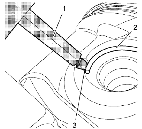
Fig. 338: Piston Pin Retainer, Remover And Notch
WARNING: Use extreme care when removing snap rings. Always wear adequate eye protection in order to avoid personal injury.
- Apply the EN-49941 remover (1) in the notch (3) to the piston pin retainer (2) and remove it.
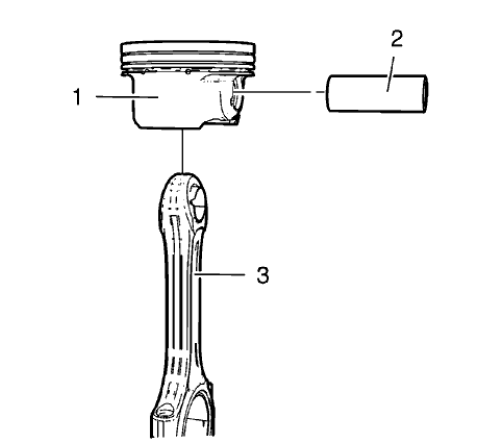
Fig. 339: Connecting Rod, Piston And Piston Pin
- Remove the piston pin (2) and the connecting rod (3) from the piston (1).
PISTON, CONNECTING ROD, AND BEARING CLEANING AND INSPECTION
Special Tools
EN-470-B Angular Torque Wrench
For equivalent regional tools, refer to Special Tools.
Visual Inspection And Cleaning Procedure
Connecting Rod
WARNING: Wear safety glasses when using compressed air in order to prevent eye injury.
- Clean the connecting rods in solvent and dry with compressed air.
- Inspect the connecting rod for the following:
- Signs of being twisted, bent, nicked or cracked
- Scratches or abrasion on the connecting rod bearing seating surfaces
Piston
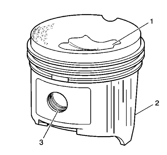
Fig. 340: Identifying Piston Damage Inspection Areas
- Clean the piston with a cleaning solvent. DO NOT wire brush any parts of the piston.
- Clean the piston ring grooves.
- Inspect the piston on the following:
- Cracked ring lands, skirts or pin bosses
- Ring grooves for nicks
- Eroded areas on the top of the piston (1)
- Scuffed or damaged skirts (2)
- Worn piston pin bores (3)
- If there is any excessive wear, replace the piston.
- Measure the clearance between piston pin and piston bore.
Piston And Connecting Rod Measurement Procedure
Piston Ring Clearance
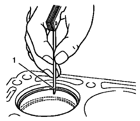
Fig. 341: Measuring Piston Ring End Clearance
- Install the piston rings to the cylinder as shown (1) and measure the piston ring end gap. Compare the measurements with those provided below:
- The upper compression ring end gap should be 0.4-0.6 mm (0.0157-0.0236 in).
- The lower compression ring end gap should be 0.4-0.6 mm (0.0157-0.0236 in).
- The oil ring end gap should be 0.2-0.9 mm (0.0079-0.0354 in).
- If the clearance is greater than the provided specifications, the piston rings must be replaced.
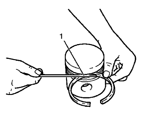
Fig. 342: Measuring Piston Ring Side Clearance
- Measure the piston ring side clearance as shown (1). Compare the measurements with those provided below:
- The upper compression ring side clearance should be 0.025-0.07 mm (0.001-0.0028 in).
- The lower compression ring side clearance should be 0.025-0.07 mm (0.001-0.0028 in).
- The oil ring side clearance should be 0.04-0.12 mm (0.0016-0.0047 in).
- If the clearance is greater than the provided specifications, replace the piston rings.
- If the clearance is still to great, replace the pistons.
Connecting Rod Bearing Clearance (With Micrometer Gauge Internal Measuring Device)
- Install the connecting bearings and the connecting rod bearing caps.
- Tighten the connecting rod bearing cap bolts in the following sequence:
CAUTION: Refer to Fastener Caution
NOTE: The old bolts can be reused for the measuring procedure.
- Tighten the connecting rod bearing cap bolts to 10 N.m (89 lb in).
- Tighten the bolts to an additional 60 degrees using EN-470-B wrench.
- Tighten the bolts to an additional 15 degrees using EN-470-B wrench.
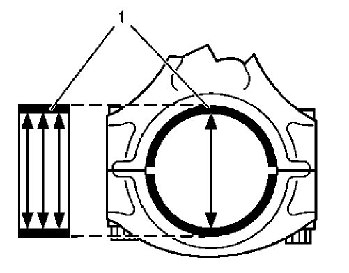
Fig. 343: Measuring Connecting Rod Bearing Diameters
- Measure the connecting rod bearing diameters at 3 points as shown (1). Use a internal measuring device.
- Calculate the average connecting rod inner diameter.
Formula: 1. result + 2. result + 3. result / 3
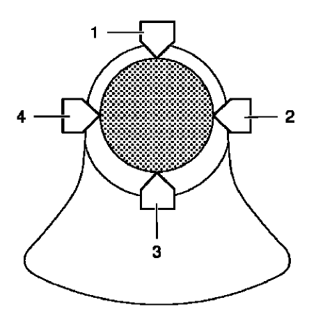
Fig. 344: Connecting Rod Journal Diameter Points
- Measure the connecting rod journal diameter at 2 points between (1) and (3) and between (2) and (4). Use a micrometer gauge.
- Calculate the average connecting rod journal diameter.
Formula: 1. result + 2. result / 2.
- Substract the average connecting rod journal diameter from the average connecting rod bearing diameter in order to determine the connecting rod bearing clearance.
The clearance should be 0.013-0.061 mm (0.0005-0.0024 in).
Piston and connecting rod assemble
Special Tools
EN-49941 Remover / Installer Piston Retainer Ring
For equivalent regional tools, refer to Special Tools.
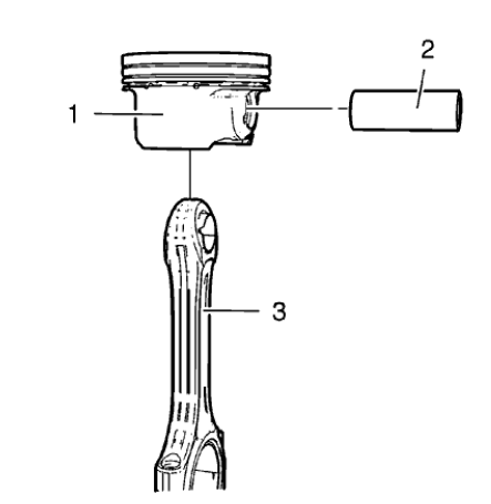
Fig. 345: Connecting Rod, Piston And Piston Pin
NOTE: Lubricate the piston pin with clean engine oil.
- Install the connecting rod (3) and the piston pin (2) to the piston (1).
- Install the piston and connecting rod assembly to a bench vise. Use aluminium braces.
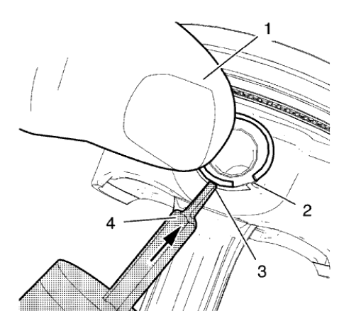
Fig. 346: Pushing Piston Pin Retainer Down With Thumb
WARNING: Use extreme care when removing snap rings. Always wear adequate eye protection in order to avoid personal injury.
WARNING: Use care when removing or installing the piston retainer ring.
Ensure the EN-49941 remover/installer is installed properly onto the retainer ring and that hands and fingers are kept clear from the front of the tool. Otherwise, bodily injury may occur.
NOTE: Notch (2) on right side.
- Place the piston pin retainer in the piston pin retainer groove so that the ring gap lays on the notch (2).
- Push the piston pin retainer down with the thumb in the shown position (1) and hold.
NOTE: The EN-49941 installer should be applied in a perpendicular position to the piston pin retainer.
- Apply the EN-49941 installer (4) to the piston pin retainer in the position shown (3) and push in direction of the arrow while pushing down with the thumb.
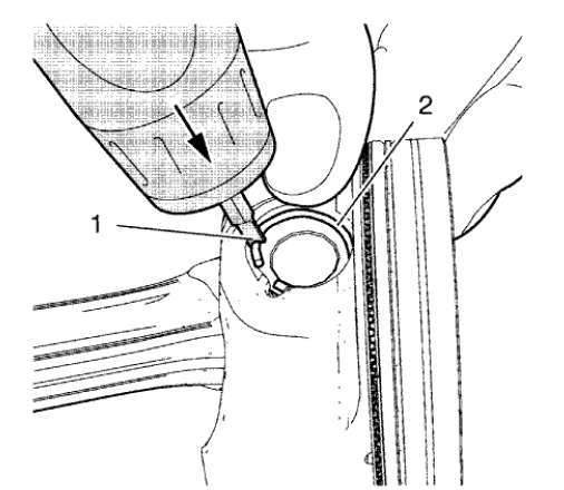
Fig. 347: Pushing Piston Pin Retainer Down
NOTE: Push the piston pin retainer down in the position shown (2).
- Move the EN-49941 installer (1) carefully to the position shown while pushing in direction of the arrow until the piston pin retainer engages in the piston pin retainer groove.
- Push down the piston ring retainer to get a proper seat in the groove.
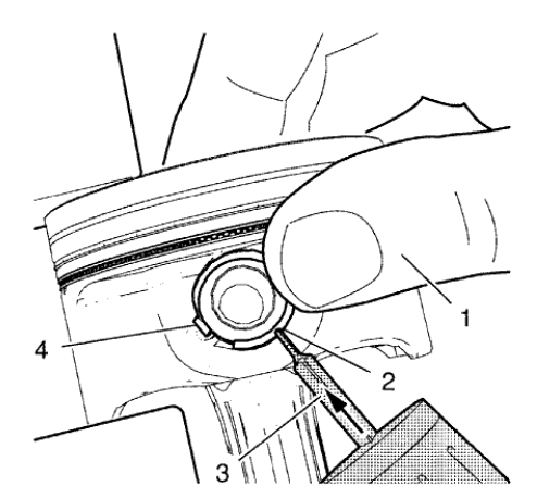
Fig. 348: Pushing Piston Pin Retainer Down With Thumb
NOTE: Notch (4) on left side. EN-49941 installer should be used with left hand.
- Place the piston pin retainer in the piston pin retainer groove so that the ring gap lays on the notch (4).
- Push the piston pin retainer down with the thumb in the position shown (1) and hold.
NOTE: The EN-49941 installer should be applied in a perpendicular position to the piston pin retainer.
- Apply the EN-49941 installer (3) to the piston pin retainer in the position shown (2) and push in direction of the arrow while pushing down with the thumb.
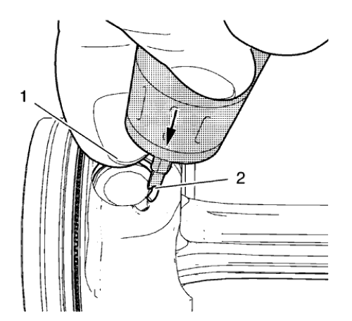
Fig. 349: Pushing Piston Pin Retainer Down
NOTE: Push the piston pin retainer down in the position shown (1).
- Move the EN-49941 installer (2) carefully to the position shown while pushing in direction of the arrow until the piston pin retainer engages in the piston pin retainer groove.
- Push down the piston ring retainer to get a proper seat in the groove.
- Remove the piston and connecting rod assembly from the bench vise.
Fig. 350: Using Piston Ring Pliers
- Install the piston rings. Use piston ring pliers (1).
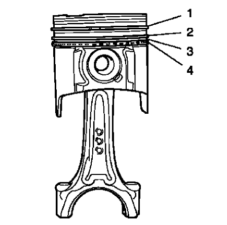
Fig. 351: Upper Compression Ring, Lower Compression Ring, Oil Rings And Oil
Ring Spacer
NOTE: Mind the TOP marking on the piston rings.
- The piston rings must be ordered as followed:
- Upper compression ring (1)
- Lower compression ring (2)
- Piston oil ring with spacer (3), (4)
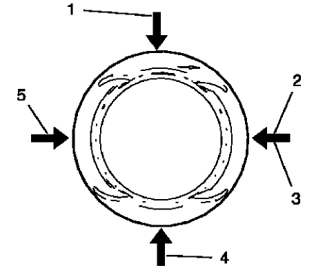
Fig. 352: Oil Ring Joints, Lower Compression Ring Joint, Upper Compression
Ring Joint And Oil Ring Spacer Joint
- The piston ring joints must be positioned 90 degrees to each other.
- Upper compression ring joint (2)
- Lower compression ring joint (5)
- Oil ring joint, upper part (1)
- Oil ring joint, lower part (4)
- Oil ring spacer joint (3)
INTAKE MANIFOLD DISASSEMBLE
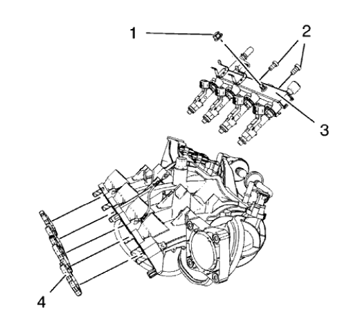
Fig. 353: Fuel Injection Fuel Rail Assembly And Intake Manifold Gasket
- Remove the fuel injection rail ground cable nut (1).
- Remove the 2 fuel injection rail bolts (2).
- Remove the fuel injection fuel rail assembly (3).
- Remove the intake manifold gasket (4).
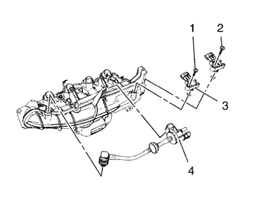
Fig. 354: Evaporative Emission Canister Purge Solenoid Valve And Manifold
Absolute Pressure Sensors
- Remove the 2 manifold absolute pressure sensor bolts (1).
- Remove the 2 manifold absolute pressure sensors (2).
- Remove the evaporative emission canister purge solenoid valve (3).
INTAKE MANIFOLD CLEANING AND INSPECTION
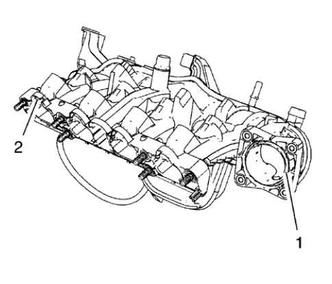
Fig. 355: Sealing Surfaces
- Clean the sealing surfaces (1) and (2).
- Inspect the intake manifold for cracks and fractures.
INTAKE MANIFOLD ASSEMBLE
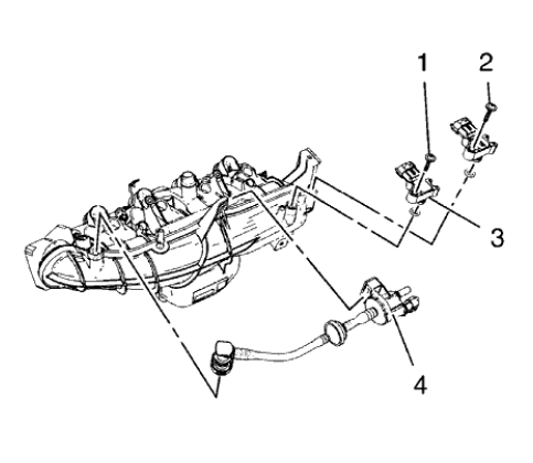
Fig. 356: Evaporative Emission Canister Purge Solenoid Valve And Manifold
Absolute Pressure Sensors
- Install the evaporative emission canister purge solenoid valve (3).
- Install the 2 manifold absolute pressure sensors (2).
- Install the 2 manifold absolute pressure sensor bolts (1) and tighten.
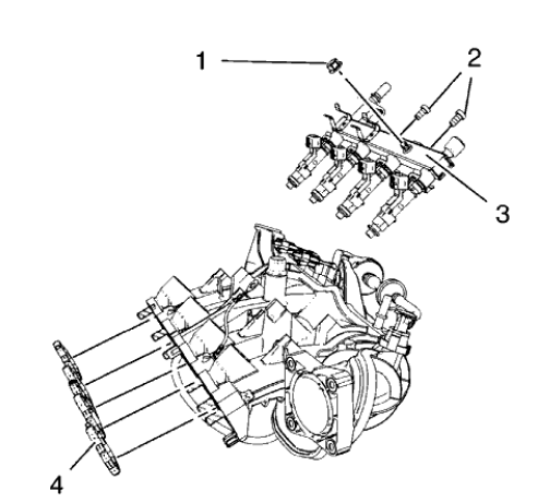
Fig. 357: Fuel Injection Fuel Rail Assembly And Intake Manifold Gasket
- Install the fuel injection fuel rail assembly (3).
CAUTION: Refer to Fastener Caution .
- Install the 2 fuel injection rail bolts (2) and tighten to 8 N.m (71 lb in).
- Install the fuel injection rail ground cable nut (1) and tighten.
- Install a NEW intake manifold gasket (4).
Crankshaft and bearing cleaning and inspection
Special Tools
- EN-470-B Angular Torque Wrench
- GE-571-B Dial Gauge
For equivalent regional tools, refer to Special Tools.
Crankshaft End Play, Check
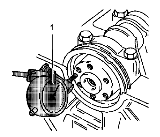
Fig. 358: Gauge Tool
NOTE: Crankshaft attached with crankshaft bearing caps.
- Install the GE-571-B gauge (1).
- Install the holder on the front of the engine block.
- Place the dial gauge plunger against the crankshaft and adjust.
- Measure the longitudinal play of the crankshaft.
- Move the crankshaft in the longitudinal direction.
- Permissible crankshaft end play 0.100-0.202 mm (0.0039-0.0080 in).
- Remove the GE-571-B gauge.
Crankshaft Out-of-Round, Check
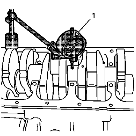
Fig. 359: Gauge Tool
NOTE: Crankshaft removed.
- Insert the crankshaft in the engine block.
- Install the GE-571-B gauge (1).
- Attach holder to the engine block.
- Place the dial gauge plunger against the crankshaft bearing journal and adjust.
- Check the rotational play of the crankshaft.
- Turn the crankshaft evenly.
- Maximum permissible rotational play 0.03 mm (0.001 in).
- Remove the GE-571-B gauge.
Check Crankshaft Bearing Clearance (With Plastigage)
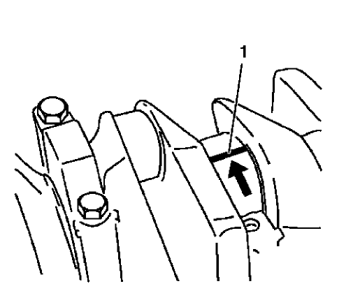
Fig. 360: Plastigage On Bearing Journal
NOTE:
- Crankshaft removed.
- Do not rotate the crankshaft.
- Lay out plastigage.
Lay out plastigage (flexible plastic thread) around the entire width of the crankshaft bearing journal (1).
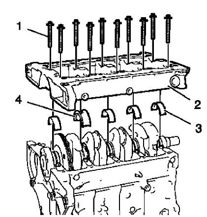
Fig. 361: Crankshaft Bearing Cap Tie Plate
NOTE: The bolts can be reused for checking the crankshaft bearing play.
- Install the 4 lower crankshaft bearings (3) and the lower crankshaft thrust bearing (4).
- Install the crankshaft bearing cap tie plate (2).
- Install the 10 inner crankshaft bearing cap tie plate bolts (1).
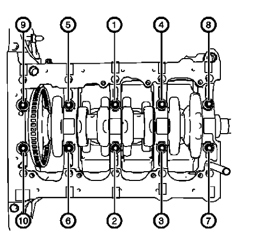
Fig. 362: Inner Crankshaft Bearing Cap Tie Plate Bolts Tightening Sequence
CAUTION: Refer to Fastener Caution .
- Tighten the 10 inner crankshaft bearing cap tie plate bolts in a sequence as shown and in the following order:
- Tighten the inner crankshaft bearing cap tie plate bolts to 25 N.m (18 lb ft).
- Tighten the inner crankshaft bearing cap tie plate bolts an additional 60º. Use EN-470-B wrench.
- Tighten the inner crankshaft bearing cap tie plate bolts an additional 15º. Use EN-470-B wrench.
- Remove the crankshaft bearing cap tie plate bolts and the crankshaft bearing cap tie plate.
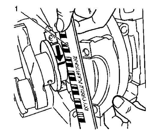
Fig. 363: Measuring Crankshaft Bearing Play Using Measuring Scale
NOTE: When reading the value, do not confuse millimeters and inches on the measuring scale.
- Measure the crankshaft bearing play.
- Compare the width of the flattened plastic thread (arrow) to the measuring scale (1).
- The crankshaft bearing play should be 0.007-0.031 mm (0.00028-0.00122 in).
Check Crankshaft Bearing Clearance (With Micrometer Gauge Internal Measuring Device)
NOTE: The bolts can be reused for checking the crankshaft bearing play.
- Install and tighten the crankshaft bearing cap tie plate and the crankshaft bearings as shown above.
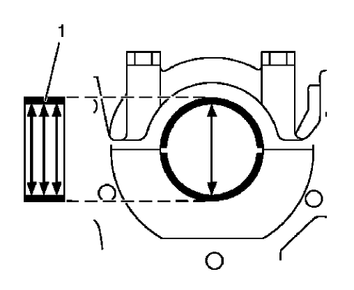
Fig. 364: Crankshaft Bearing Diameter Measuring Points
- Measure the crankshaft bearing diameter at 3 points.
Measure in areas as shown (1) with an internal measuring device.
Calculate the average crankshaft bearing diameter.
Formula: 1. result + 2. result + 3. result / 3.
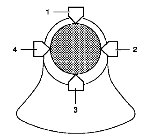
Fig. 365: Connecting Rod Journal Diameter Points
- Measure the crankshaft bearing journal diameter at 2 points between (1) and (3) and between (2) and (4) with the micrometer gauge.
- Calculate the average crankshaft bearing journal diameter.
Formula: 1. result + 2. result / 2.
- Determine the crankshaft bearing play.
Calculation formula: average crankshaft bearing diameter minus average crankshaft bearing journal diameter.
- The crankshaft bearing play should be 0.007-0.031 mm (0.00028-0.00122 in).
Engine front cover and oil pump cleaning and inspection
Engine Front Cover Cleaning Procedure
- Clean the engine front cover sealing surface.
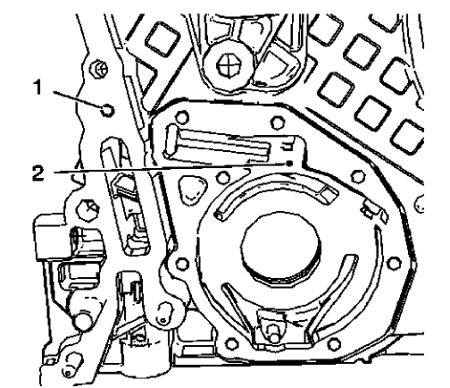
Fig. 366: Oil Gallery Bores
WARNING: Wear safety glasses when using compressed air in order to prevent eye injury.
CAUTION: To ensure proper engine lubrication, clean clogged or contaminated oil galleries in an approved solvent and with compressed air. Failure to clean oil galleries may cause engine damage.
- Clean the shown oil gallery with solvent and compressed air. Blow compressed air from bore (2) to bore (1).
Engine Front Cover Visual Inspection
Inspect the engine front cover for cracks, scratches and damage.
Oil Pump Visual Inspection and Measurement
- Inspect the oil pump cover and the engine front cover for flatness.
- Inspect the oil pump vanes, the oil pump vane rotor, the oil pump vane rings and the oil pump slide for localized flatting.
- Inspect the oil pump slide pivot pin for firm seat.
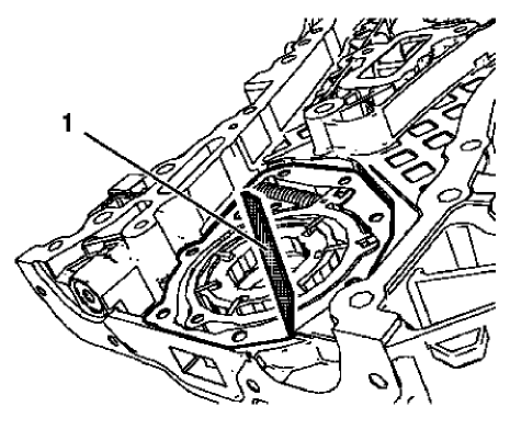
Fig. 367: Straight Edge Tool
NOTE: Oil pump components are installed.
- Measure the oil pump axial clearances. Use a straight edge (1) and a feeler gauge.
- The maximal axial clearance between engine front cover and oil pump vane rotor should be 0.1 mm (0.004 in).
- The maximal axial clearance between engine front cover and oil pump vane should be 0.09 mm (0.0035 in).
- The maximal axial clearance between engine front cover and oil pump vane ring should be 0.4 mm (0.016 in).
- The maximal axial clearance between engine front cover and oil pump slide should be 0.08 mm (0.0031 in).
- The maximal axial clearance between engine front cover and oil pump slide seal should be 0.09 mm (0.0035 in).
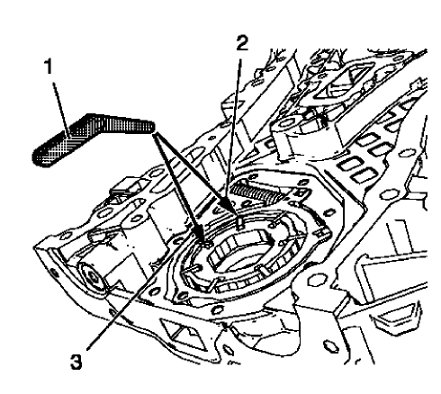
Fig. 368: Feeler Gauge, Oil Pump Slide And Oil Pump Vane
- Measure the oil pump radial clearance. Use a feeler gauge (1). Measure the clearance between oil pump vane rotor and oil pump vane (3).
The maximal clearance should be 0.05 mm (0.002 in).
- Measure the clearance between oil pump vane and oil pump slide (2).
The maximal clearance should be 0.2 mm (0.008 in).
ENGINE FRONT COVER AND OIL PUMP DISASSEMBLE
Engine Front Cover Disassemble
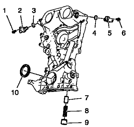
Fig. 369: Locating Engine Front Cover Components
- Remove the intake camshaft position sensor bolt (1).
- Remove the intake camshaft position sensor (2) and the seal ring (3).
- Remove the exhaust camshaft position sensor bolt (6).
- Remove the exhaust camshaft position sensor (5) and the seal ring (4).
- Remove the oil pressure relief valve (7, 8 and 9)
- Remove the crankshaft front oil seal (10).
Oil Pump Removal
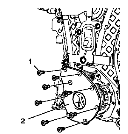
Fig. 370: Engine Oil Pump Cover And Bolts
- Remove the 8 oil pump cover bolts (1).
- Remove the oil pump cover (2).
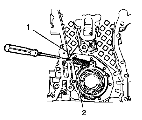
Fig. 371: Oil Pump Slide Spring Windings And Engine Front Cover Edge
WARNING: Before removing the spring, cover the spring with a towel to prevent the spring from flying and possibly causing damage or personal injury.
NOTE: Position a screw driver between the oil pump slide spring windings (2).
- Protect the engine front cover edge (1) with a suitable piece of plastic.
- Compress the oil pump slide spring with a screw driver and remove the oil pump slide spring along with the oil pump slide spring pin.
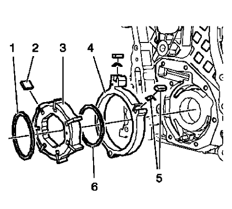
Fig. 372: Locating Engine Oil Pump Components
NOTE: Mind the installation position of the oil pump components.
- Remove the oil pump components in the following order:
- Outer oil pump vane ring (1).
- Oil pump vane rotor (3) and the 7 oil pump vanes (2).
- Inner oil pump vane ring (6).
- Oil pump slide (4) and the 2 oil pump slide seals with the 2 oil pump slide seal springs (5).
TURBOCHARGER DISASSEMBLE
Special Tool
EN-49940 Remover Quick Connector
For equivalent regional tools, refer to Special Tools.
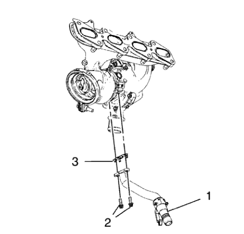
Fig. 373: Turbocharger Oil Return Pipe
- Remove the 2 turbocharger oil return pipe bolts (2).
- Remove the turbocharger oil return pipe (1) and the sealing (3) from the turbocharger.
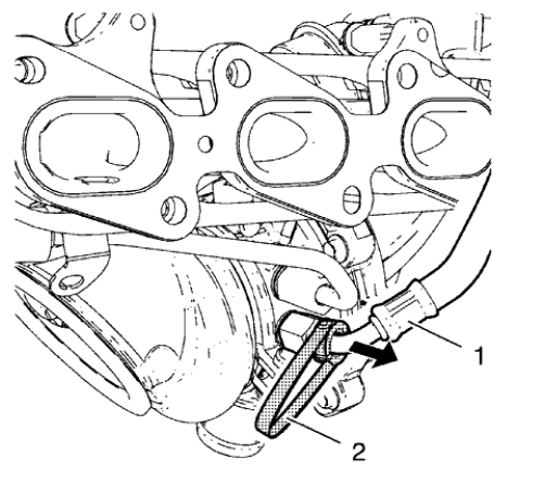
Fig. 374: Turbocharger Coolant Feed Pipe
NOTE: The quick fitting connectors should be always replaced when the turbocharger coolant pipes are removed
- Install the EN-49940 remover (2) to the turbocharger coolant feed pipe (1) and the quick fitting connector as shown.
- Compress the EN-49940 remover and remove the turbocharger coolant feed pipe direction of the arrow.
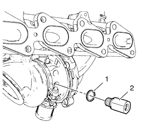
Fig. 375: Quick Fitting Connector And Seal Ring
- Remove the quick fitting connector (2) and the seal ring (1).
- Use the same procedure for the turbocharger coolant return pipe and the turbocharger coolant return pipe quick fitting connector.
TURBOCHARGER CLEANING AND INSPECTION
Cleaning Procedure
- Clean all sealing surfaces.
- Clean all threads if necessary.
Inspection Procedure
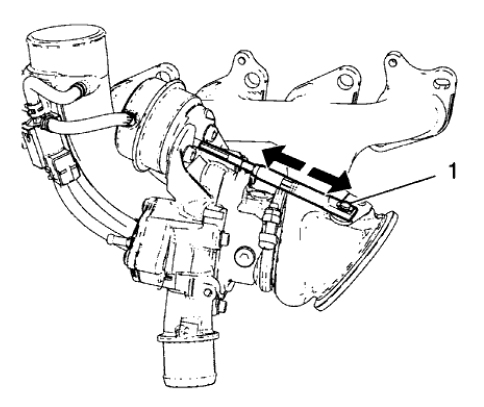
Fig. 376: Wastegate Regulator Mechanism
- Inspect the wastegate regulator mechanism (1) for functionality.
- Inspect the turbine blades for damage or foreign material.
- Inspect the turbocharger wastegate regulator vacuum hoses for damage.
- Inspect the exhaust manifold and the turbocharger for cracks or other damage.
- Inspect the exhaust manifold mating surface for flatness.
TURBOCHARGER ASSEMBLE
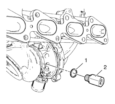
Fig. 377: Quick Fitting Connector And Seal Ring
CAUTION: Refer to Fastener Caution .
- Install the NEW quick fitting connector (2) and a NEW seal ring (1) to the turbocharger and tighten to 20 N.m (15 lb ft).
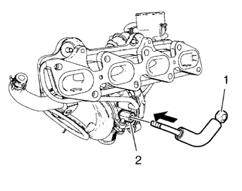
Fig. 378: Turbocharger Coolant Feed Pipe And Quick Fitting Connector
- Inspect the turbocharger coolant pipes for ridges and damage.
- Install the turbocharger coolant feed pipe (1) to the quick fitting connector (2) by pushing in direction of the arrow until an audible click is heard.
- Use the same procedure for the turbocharger coolant return pipe and the turbocharger coolant return pipe quick fitting connector.
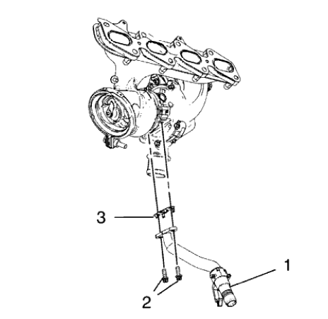
Fig. 379: Turbocharger Oil Return Pipe
- Install the turbocharger oil return pipe (1) and a NEW sealing (3) to the turbocharger.
- Install the 2 turbocharger oil return pipe bolts (2) and tighten to 8 N.m (71 lb in).
ENGINE OIL COOLER DISASSEMBLE
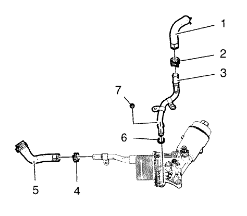
Fig. 380: Locating Engine Oil Cooler Components
- Remove the oil cooler coolant inlet hose clamp (2).
- Remove the oil cooler coolant inlet hose (1).
- Remove the oil cooler coolant inlet pipe bolt (7)
- Remove the oil cooler coolant inlet pipe (3) and the seal ring (6).
- Remove the oil cooler coolant outlet hose clamp (4).
- Remove the oil cooler coolant outlet hose (5).
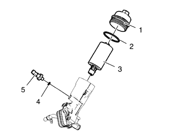
Fig. 381: Engine Oil Pressure Indicator Switch, Oil Filter Cap And Oil Filter
Element
- Remove the engine oil pressure indicator switch (5) and the seal ring (4).
- Remove the engine oil filter cap (1) along with the seal ring (2) and the oil filter element (3).
ENGINE OIL COOLER ASSEMBLE
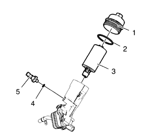
Fig. 382: Engine Oil Pressure Indicator Switch, Oil Filter Cap And Oil Filter
Element
CAUTION: Refer to Fastener Caution .
- Install the engine oil filter cap (1) along with a NEW seal ring (2) and a NEW oil filter element (3) and tighten to 25 N.m (18 lb ft).
- Install the engine oil pressure indicator switch (5) and NEW seal ring (4) and tighten to 20 N.m (15 lb ft).
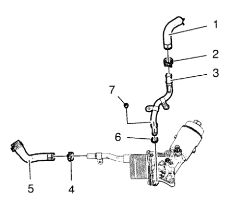
Fig. 383: Locating Engine Oil Cooler Components
- Install the oil cooler coolant outlet hose (5)
- Install the oil cooler coolant outlet hose clamp (4).
- Install the oil cooler coolant inlet pipe (3) and a NEW seal ring (6).
- Install the oil cooler coolant inlet pipe bolt (7) and tighten to 10 N.m (89 lb in).
- Install the oil cooler coolant inlet hose (1).
- Install oil cooler coolant inlet hose clamp (2).
OIL PAN CLEANING AND INSPECTION
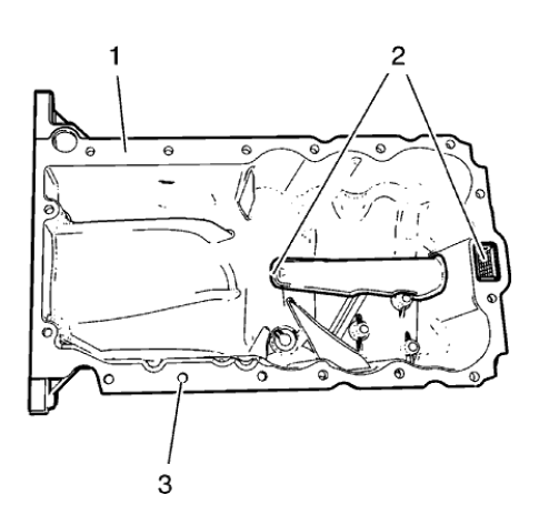
Fig. 384: Oil Suction Gallery, Sealing Surface And Screw Bores
WARNING: Wear safety glasses when using compressed air in order to prevent eye injury.
CAUTION: To ensure proper engine lubrication, clean clogged or contaminated oil galleries in an approved solvent and with compressed air. Failure to clean oil galleries may cause engine damage.
- Clean the oil suction gallery (2) with compressed air. Be sure to remove all dirt and old gasket material from the suction gallery (2).
- Remove all remaining old gasket material from sealing surface (1) and screw bores (3).
- Clean the sealing surfaces from dirt and grease.
- Inspect the sealing surface for cracks and damage.
Crankshaft and bearing installation
Special Tools
- EN-235-6 Installer from EN-235-D Kit.
- EN-470-B Angular Torque Wrench
- EN-658-1 Installer from EN-658 Kit
For equivalent regional tools, refer to Special Tools.
- Lubricate crankshaft, crankshaft bearings and crankshaft bearing cap tie plate with engine oil.
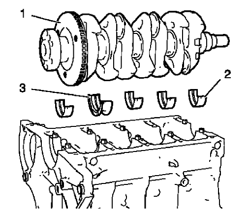
Fig. 385: Crankshaft, Upper Crankshaft Bearings And Upper Crankshaft Thrust
Bearing
- Install the 4 upper crankshaft bearings (2) and the crankshaft thrust bearing (3).
- Install the crankshaft (1).
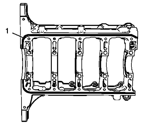
Fig. 386: Sealing Compound Application Area
NOTE: The thickness of the sealing bead should be 2 mm (0.0787 in).
- Apply sealing compound (1) to the outer rim of the groove on the crankshaft bearing cap tie plate. Refer to Adhesives, Fluids, Lubricants, and Sealers.
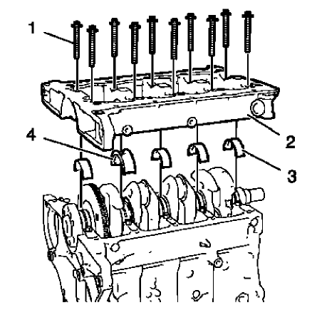
Fig. 387: Crankshaft Bearing Cap Tie Plate
NOTE: The complete installation procedure should not take longer than 10 minutes.
- Install the 4 lower crankshaft bearings (3) and the lower crankshaft thrust bearing (4).
- Install the crankshaft bearing cap tie plate (2).
NOTE: Do not reuse the old bolts.
- Install the 10 NEW inner crankshaft bearing cap tie plate bolts (1).
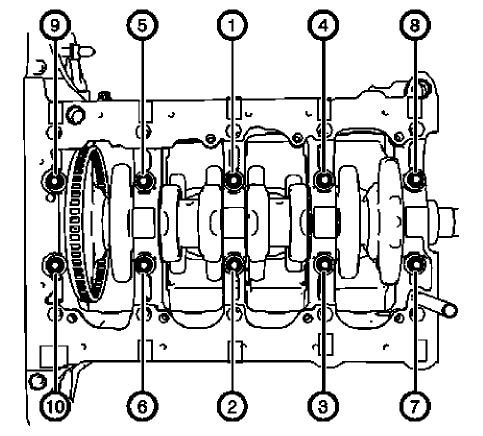
Fig. 388: Inner Crankshaft Bearing Cap Tie Plate Bolts Tightening Sequence
CAUTION: Refer to Fastener Caution .
CAUTION: Refer to Torque-to-Yield Fastener Caution .
- Tighten the 10 inner crankshaft bearing cap tie plate bolts in the sequence shown and to the following specifications:
- Tighten the inner crankshaft bearing cap tie plate bolts to 25 N.m (18 lb ft).
- Tighten the inner crankshaft bearing cap tie plate bolts an additional 60 degrees. Use EN-470-B wrench.
- Tighten the inner crankshaft bearing cap tie plate bolts an additional 15 degrees. Use EN-470-B wrench.
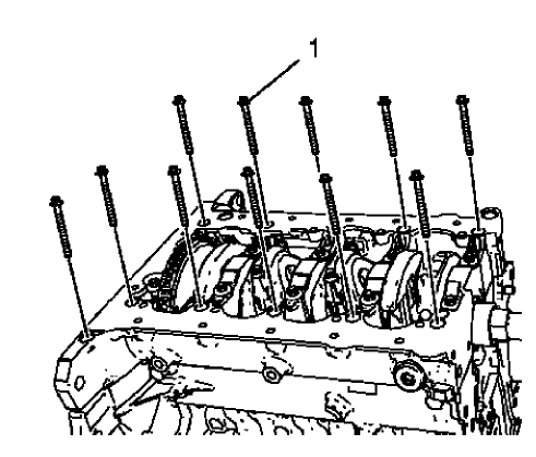
Fig. 389: Outer Crankshaft Bearing Cap Tie Plate Bolts
NOTE: Do not reuse the old bolts.
- Install the 12 NEW outer crankshaft bearing cap tie plate bolts (1) and tighten to the following specification:
- Tighten the outer crankshaft bearing cap tie plate bolts to 10 N.m (89 lb in).
- Tighten the outer crankshaft bearing cap tie plate bolts an additional 60 degrees. Use EN-470-B wrench.
- Tighten the outer crankshaft bearing cap tie plate bolts an additional 15 degrees. Use EN-470-B wrench.
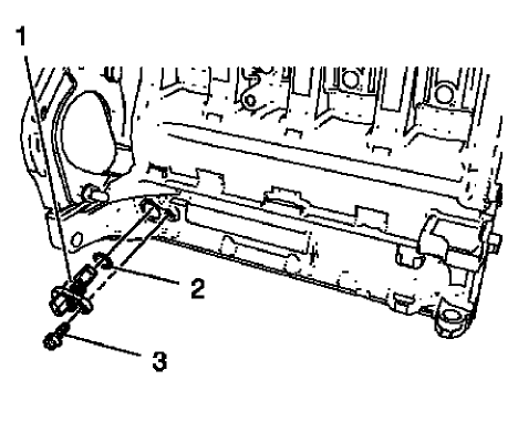
Fig. 390: Crankshaft Position Sensor, Bolt And Seal Ring
- Install the crankshaft position sensor (1) and a NEW crankshaft position sensor seal ring (2).
- Install the crankshaft position sensor bolt (3) and tighten to 8 N.m (71 lb in).
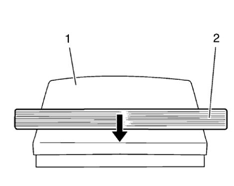
Fig. 391: Crankshaft Rear Oil Seal
- Slide the crankshaft rear oil seal (2) across the EN-235-6 installer (1) contained in EN-235-D kit.
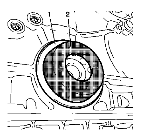
Fig. 392: Crankshaft Rear Oil Seal And Installer
- Install the crankshaft rear oil seal (1) with EN-235-6 installer (2) to the crankshaft.
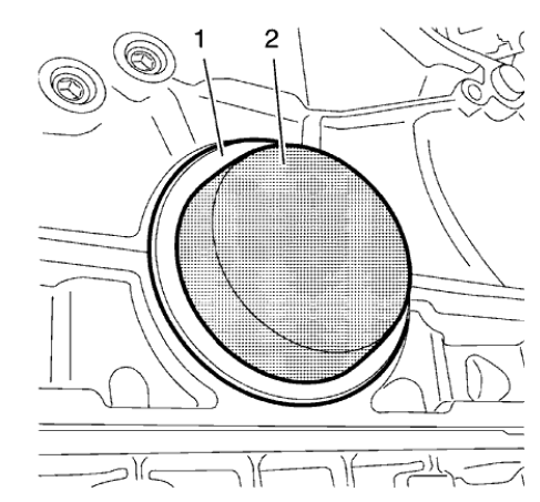
Fig. 393: Oil Seal Installer
NOTE: Ensure that the crankshaft rear oil seal fits proper.
- Use EN-658-1 installer (2) to strike the crankshaft rear oil seal (1)
PISTON, CONNECTING ROD, AND BEARING INSTALLATION
Special Tools
EN-470-B Angular Torque Wrench
For equivalent regional tools, refer to Special Tools.
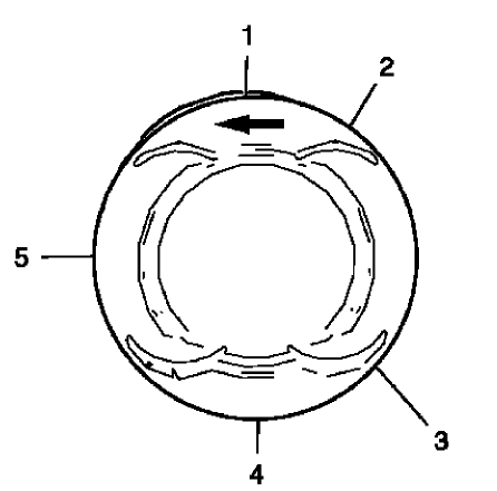
Fig. 394: Piston Ring Joint Adjustment Points
- Adjust the piston ring joints as follows:
- Upper compression ring (1).
- Lower compression ring (4).
- Oil rings (2) or (3).
- Oil ring spacer (5)
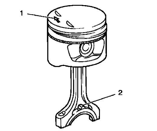
Fig. 395: Rods And Arrow On Piston Head
- The arrow (1) on the piston head must point to the timing side.
- The markings on the connecting rods (2) must point to the transmission side.
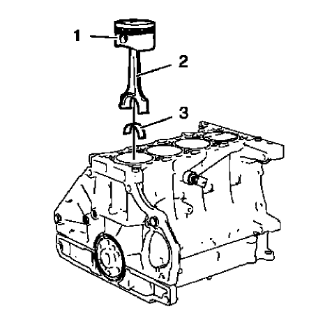
Fig. 396: Pistons, Connecting Rods And Bearings
- Install a piston ring compressor to compress the piston rings.
- Install the pistons (1) in along with connecting rods (2) and upper connecting rod bearings (3) to the engine block and to the crankshaft.
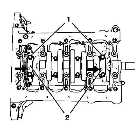
Fig. 397: Rod Bearing Caps And Bolts
NOTE: The flarings (arrows) on the connecting rod bearing caps must point to the transmission side. The connecting rod bearing caps must be installed in their original position.
- Install the 2 connecting rod bearings and the 2 connecting rod bearing caps (2) of cylinder 1 and 4.
CAUTION: Refer to Fastener Caution
CAUTION: Refer to Torque-to-Yield Fastener Caution .
NOTE: Do not reuse the old bolts.
- Install the 4 NEW connecting rod bearing cap bolts (1) and tighten in the following sequence:
- Tighten the connecting rod bearing cap bolts to 25 N.m (18 lb ft).
- Tighten the connecting rod bearing cap bolts an additional 45 degrees. Use EN-470 B wrench
- Rotate the crankshaft 180 degrees.
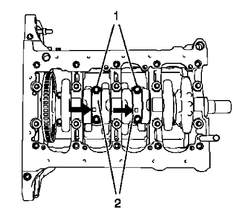
Fig. 398: Rod Bearing Caps And Bolts
NOTE: The flarings (arrows) on the connecting rod bearing caps must point to the transmission side. The connecting rod bearing caps must be installed in their original position.
- Install the 2 connecting rod bearings and the 2 connecting rod bearing caps (2) of cylinder 3 and 2.
NOTE: Do not reuse the old bolts.
- Install the 4 NEW connecting rod bearing cap bolts (1) and tighten in the following sequence:
- Tighten the connecting rod bearing cap bolts to 25 N.m (18 lb ft).
- Tighten the connecting rod bearing cap bolts an additional 45 degrees. Use EN-470-B wrench.
Cylinder head installation
Special Tools
EN-470-B Angular Torque Wrench.
For equivalent regional tools, refer to Special Tools.
WARNING: Wear safety glasses when using compressed air in order to prevent eye injury.
- Clean the sealing surfaces and remove dirt and old gasket material from thread bores, water galleries and oil galleries.
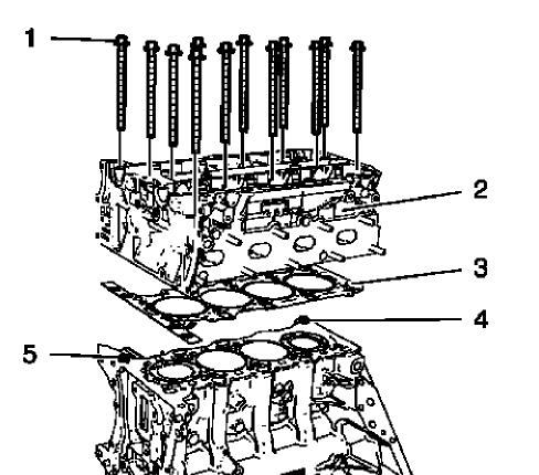
Fig. 399: Cylinder Head, Gasket, Bolts And Guide Sleeves
NOTE: Mind the guide sleeves (4) and (5).
- Install a NEW cylinder head gasket (3). The marking "Top" should point to the cylinder head.
- Install the cylinder head (2).
- Install 12 NEW cylinder head bolts (1) and hand tighten.
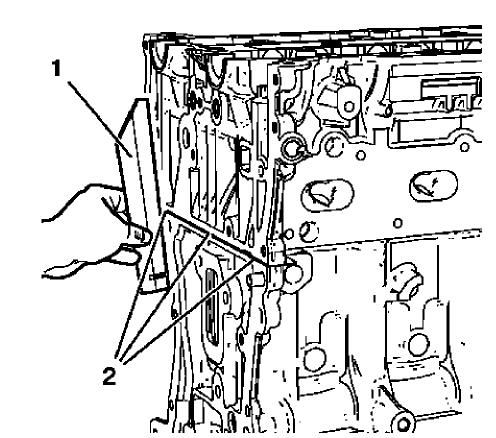
Fig. 400: Straight Edge Tool
- Lay a straight edge (1) against the engine block and cylinder head. Adjust the transition in area (2) until there is no clearance between cylinder head and straight edge, using a rubber mallet.
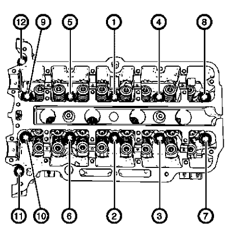
Fig. 401: Cylinder Head Bolts Tightening Sequence
CAUTION: Refer to Fastener Caution
CAUTION: Refer to Torque-to-Yield Fastener Caution .
- Tighten the cylinder head bolts in the sequence shown and to the following specifications:
- Tighten the cylinder head bolts to 35 N.m (26 lb ft).
- Tighten the cylinder head bolts an additional 180 degrees. Use EN-470-B wrench.
HYDRAULIC VALVE LASH ADJUSTER INSTALLATION
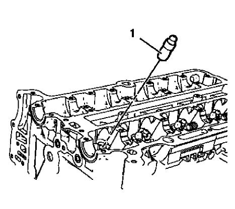
Fig. 402: Hydraulic Valve Lash Adjusters
NOTE: Mind the installation position of the hydraulic valve lash adjusters.
- Lubricate the hydraulic valve lash adjusters with engine oil.
- Install the 16 hydraulic valve lash adjusters (1).
HYDRAULIC VALVE LASH ADJUSTER ARM INSTALLATION
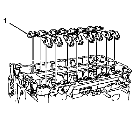
Fig. 403: Hydraulic Valve Lash Adjuster Arms
NOTE: Hydraulic valve lash adjuster arms should be installed in their original position.
- Lubricate the hydraulic valve lash adjuster arms with engine oil.
- Install the 16 hydraulic valve lash adjuster arms (1).
INTAKE CAMSHAFT INSTALLATION
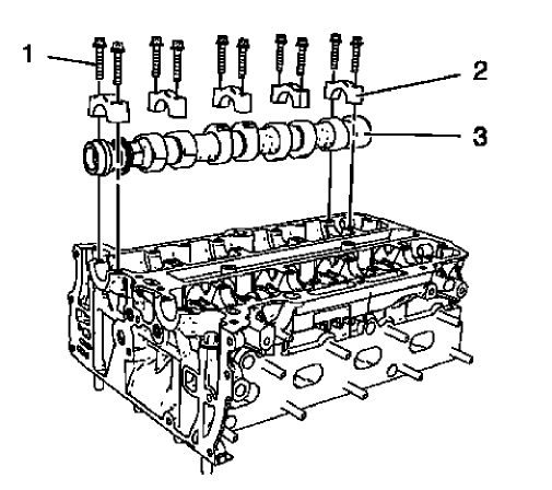
Fig. 404: Intake Camshaft, Camshaft Bearing Caps And Bolts
NOTE: Mind the markings on the camshaft bearing caps. Camshaft bearing caps should be installed in their original position.
- Lubricate camshaft and camshaft bearing caps with engine oil.
- Install the intake camshaft (3).
- Install the 5 camshaft bearing caps (2).
- Install the 10 camshaft bearing cap bolts (1) and handtighten
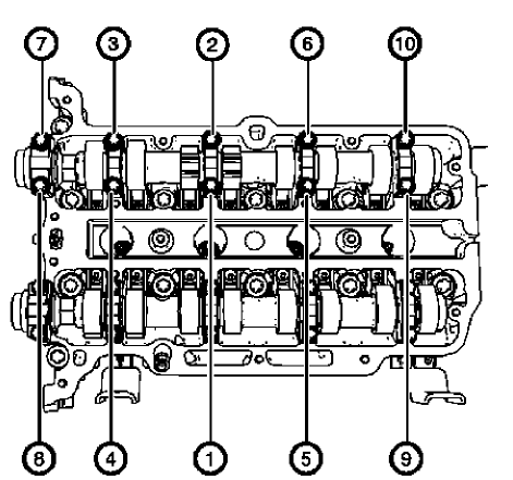
Fig. 405: Intake Camshaft Bearing Cap Bolts Tightening Sequence
CAUTION: Refer to Fastener Caution .
NOTE: Tighten the camshaft bearing cap bolts one turn at a time in order to avoid shape distortion of the camshaft.
- Tighten the camshaft bearing cap bolts one turn at a time and in a spiral sequence as shown to 8 N.m (71 lb in).
EXHAUST CAMSHAFT INSTALLATION
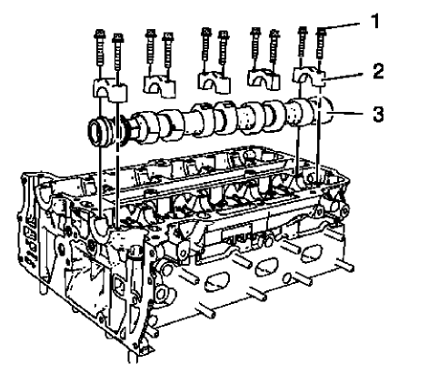
Fig. 406: Exhaust Camshaft, Camshaft Bearing Caps And Bolts
NOTE: Mind the markings on the camshaft bearing caps. Camshaft bearing caps should be installed in their original position.
- Lubricate camshaft and camshaft bearing caps with engine oil.
- Install the exhaust camshaft (3).
- Install the 5 camshaft bearing caps (2).
- Install the 10 camshaft bearing cap bolts (1) and handtighten.
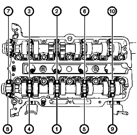
Fig. 407: Exhaust Camshaft Bearing Cap Bolts Tightening Sequence
CAUTION: Refer to Fastener Caution .
NOTE: Tighten the camshaft bearing cap bolts one turn at a time in order to avoid shape distortion of the camshaft.
- Tighten the camshaft bearing cap bolts one turn at a time and in a spiral sequence as shown to 8 N.m (71 lb in).
CAMSHAFT SPROCKET INSTALLATION
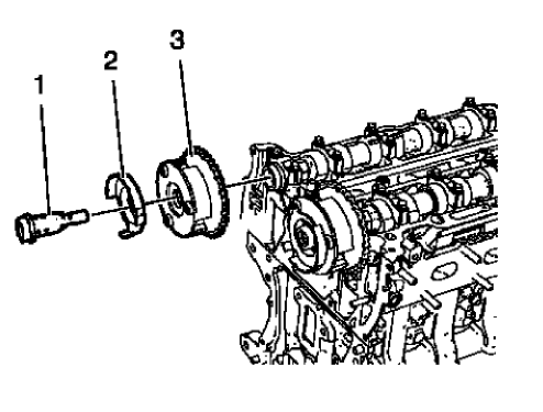
Fig. 408: Intake Camshaft Sprocket, Bolt And Intake Camshaft Position Exciter
Wheel
- Install the intake camshaft sprocket (3).
- Install the intake camshaft position sensor exciter wheel (2) and the intake camshaft sprocket bolt (1), but do not tighten yet.
- Install the exhaust camshaft sprocket.
NOTE: Tightening of camshaft sprocket bolts will be done after the engine front cover installation.
- Install the exhaust camshaft position sensor exciter wheel and the exhaust camshaft sprocket bolt, but do not tighten yet.
TIMING CHAIN TENSIONER INSTALLATION
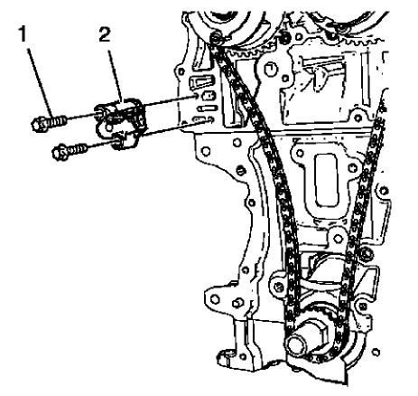
Fig. 409: Timing Chain Tensioner And Bolts
- Install the timing chain tensioner (2).
CAUTION: Refer to Fastener Caution .
- Install the 2 timing chain tensioner bolts (1) and tighten to 8 N.m (71 lb in).
ENGINE FRONT COVER GASKET INSTALLATION
- Clean the sealing surfaces and remove all remains of old sealing compound material.
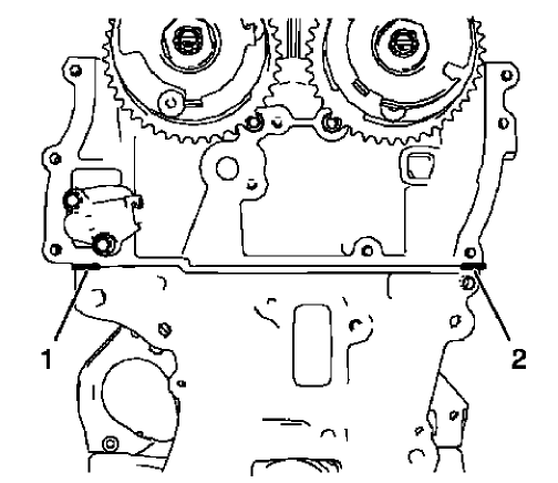
Fig. 410: Sealing Compound Application Areas
NOTE: The thickness of the sealing bead should be 2 mm (0.0787 in).
- Apply sealing compound to the shown areas (1) and (2). Refer to Adhesives, Fluids, Lubricants, and Sealers.
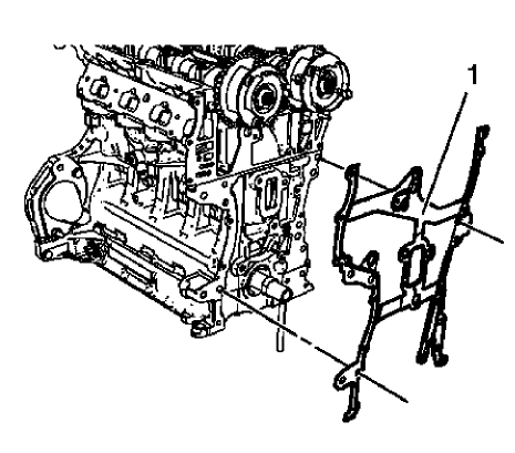
Fig. 411: Engine Front Cover Gasket
NOTE: Mind the guide sleeves.
- Install the NEW engine front cover gasket (1).
- Install the timing chain. Refer to Camshaft Timing Chain Installation.
NOTE: The complete installation procedure should not take longer than 10 minutes.
- Install the engine front cover. Refer to Engine Front Cover and Oil Pump Installation.
Camshaft timing chain installation
Special Tools
- EN-952 Fixing Pin
- EN-953-A Fixing Tool
- EN-955-10 Fixing Pin from EN-955 Kit
For equivalent regional tools, refer to Special Tools.
- The engine should be adjusted to TDC.
- The crankshaft should be locked with EN-952 fixing pin.
- The camshaft should be locked with EN-953-A fixing tool.
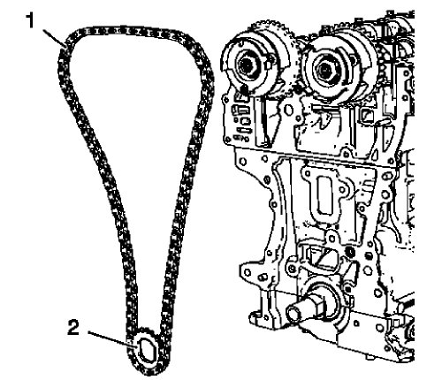
Fig. 412: Timing Chain And Crankshaft Sprocket
- Install the timing chain (1) along with the crankshaft sprocket (2).
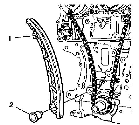
Fig. 413: Timing Chain Tensioner Shoe And Bolt
- Install the timing chain tensioner shoe (1).
CAUTION: Refer to Fastener Caution .
- Install the timing chain tensioner shoe bolt (2) and tighten to 20 N.m (15 lb ft).
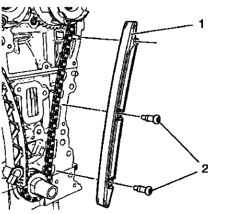
Fig. 414: Timing Chain Guide Right Side
- Install the timing chain guide right side (1).
- Install the 2 timing chain guide right side bolts (2) and tighten to 8 N.m (71 lb in).
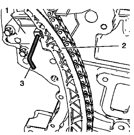
Fig. 415: Timing Chain And Timing Chain Tensioner
- Push the timing chain (2) in direction to the timing chain tensioner (1) and remove the EN-955-10 fixing pin (3).
The upper timing chain guide will be installed after the installation of the engine front cover and the fastening of the camshaft sprockets.
ENGINE FRONT COVER AND OIL PUMP INSTALLATION
Special Tools
- EN-952 Fixing Pin
- EN-953-A Fixing Tool
- EN-49977-100 Transmitter Disc Fixation
- EN-49977-200 Fixing Tool
For equivalent regional tools, refer to Special Tools.
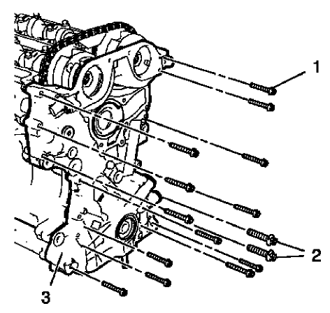
Fig. 416: M6, M10 Front Cover Bolts And Engine Front Cover
NOTE: Mind the guide sleeves when installing engine front cover.
- Install the engine front cover (3).
- Install the 13 engine front cover bolts M6 (1).
- Install the 2 engine front cover bolts M10 (2).
CAUTION: Refer to Fastener Caution .
- Tighten the 13 engine front cover bolts M6 to 8 N.m (71 lb in).
- Tighten the 2 engine front cover bolts M10 to 35 N.m (26 lb ft).
Camshaft Sprocket Fastening
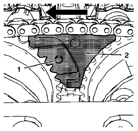
Fig. 417: Intake Camshaft Sprocket Gearing And Special Tool
NOTE: Push the fixing tool in the direction of the arrow to ensure it fully engages.
- Install EN-49977-200 fixing tool (2) and ensure that the gearing of the fixing tool engages with the intake camshaft sprocket gearing (1).
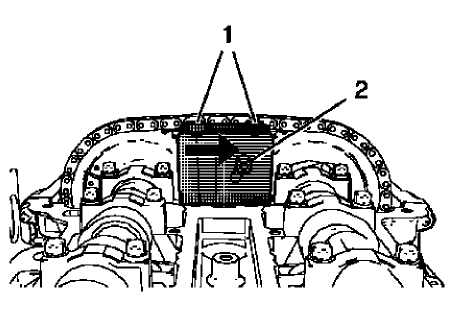
Fig. 418: Adjuster Bolt And Fastening Bolts
- Tighten the 2 fastening bolts (1) of EN-49977-200 fixing tool while pushing the fixing tool in direction of the arrow.
- Tighten the adjuster bolt (2).
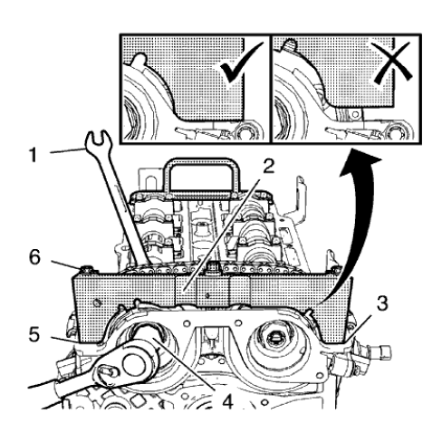
Fig. 419: Fastening Bolts And Fixation Tool
NOTE: A wrong installation position is possible. Make sure that the holding tool is fully installed to the cylinder head in areas (3) and (5).
- Install EN-49977-100 transmitter disc holder (2) to find and hold the correct position of the camshaft position exciter wheels.
- Tighten the fastening bolts (6) of EN-49977-100 transmitter disc holder.
CAUTION: Refer to Fastener Caution .
CAUTION: Refer to Torque-to-Yield Fastener Caution .
- Tighten the NEW intake camshaft sprocket bolt (4) while holding the hexagon (1) of the intake camshaft to 50 N.m (37 lb ft).
- Tighten the intake camshaft sprocket bolt (4) while holding the hexagon (1) of the intake camshaft to an additional 60 degrees.
- Tighten the NEW exhaust camshaft sprocket bolt while holding the hexagon of the exhaust camshaft to 50 N.m (37 lb ft).
- Tighten the exhaust camshaft sprocket bolt while holding the hexagon of the exhaust camshaft to an additional 60 degrees.
- Remove EN-49977-100 transmitter disc holder and EN-49977-200 fixing tool.
Upper Timing Chain Guide Installation
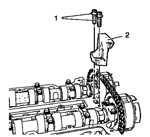
Fig. 420: Upper Timing Chain Guide And Bolts
- Install the upper timing chain guide (2).
- Install the 2 upper timing chain guide bolts (1) and tighten to 8 N.m (71 lb in).
- Remove EN-953-A fixing tool and EN-952 fixing pin.
- Install crankshaft bearing cap tie plate hole plug and seal ring and tighten to 50 N.m (37 lb ft).
Oil pan installation
Special Tools
EN-49980 Guidance Pins
For equivalent regional tools, refer to Special Tools.
- Clean the sealing surfaces from old sealing material, dirt, oil and grease.
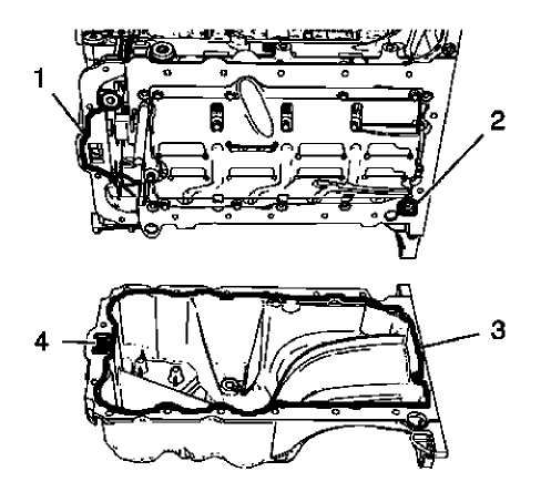
Fig. 421: Engine Front Cover, Oil Suction Gallery And Screw Bore
NOTE: The sealing bead should be applied close to the inner edge of the oil pan.
Take care that the oil suction gallery (4) will not get contaminated with sealing compound or dirt. The thickness of the sealing bead (3) should be 2 mm (0.0787 in).
- Apply sealing compound to the oil pan. Refer to Adhesives, Fluids, Lubricants, and Sealers.
- Apply sealing compound to the groove of the engine front cover (1). Refer to Adhesives, Fluids, Lubricants, and Sealers.
- Apply sealing compound around the screw bore (2) of the crankshaft bearing cap tie plate.
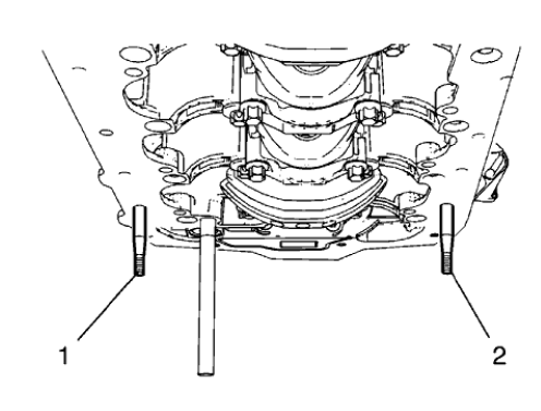
Fig. 422: Engine Oil Pan Pins
NOTE: The complete installation procedure of the oil pan should not take longer than 10 minutes.
- Install the 2 EN-49980 pins (1) and (2) to the shown oil pan screw bores.
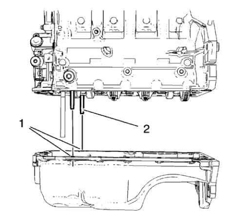
Fig. 423: Engine Oil Pan Pins And Screw Bores
CAUTION: Use care when installing the oil pan to prevent disruption of the sealing bead. The sealing bead should remain consistent until the oil pan is mated with the engine. An inconsistent sealing bead can cause an insufficient seal and result in engine damage.
- Carefully install the oil pan. Guide the oil pan with EN-49980 pins (2) and the equivalent screw bores (1).
- Hold the oil pan with 4 oil pan bolts.
- Remove EN-49980 pins.
- Install the remaining 12 oil pan bolts and hand tighten.
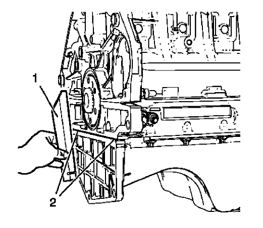
Fig. 424: Straight Edge Tool
- Lay a straight edge (1) against the oil pan and engine block. Using a rubber mallet, adjust the transition in area (2) until there is no clearance between oil pan and the straight edge.
CAUTION: Refer to Fastener Caution .
- Tighten the 16 oil pan bolts to 10 N.m (89 lb in).
CAMSHAFT POSITION ACTUATOR SOLENOID VALVE INSTALLATION
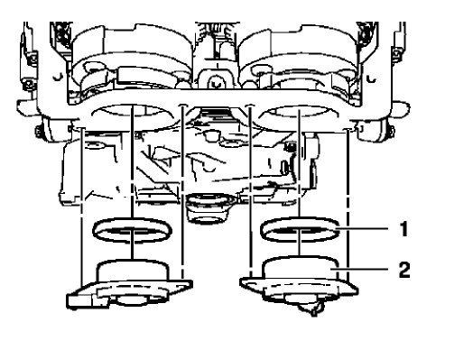
Fig. 425: Camshaft Position Actuator Solenoid Valves And Seal Rings
CAUTION: The camshaft position actuator solenoid valves must be kept parallel to the engine front cover during removal and installation. The camshaft position actuator solenoid valves can be damaged if they become wedged or stuck during this process.
- Install the 2 camshaft position actuator solenoid valves (2) and the 2 seal rings (1) by carefully and evenly pressing.
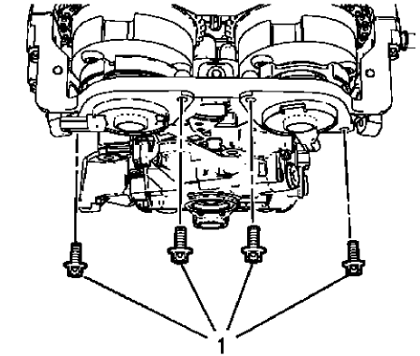
Fig. 426: Camshaft Position Actuator Solenoid Valve Bolts
CAUTION: Refer to Fastener Caution
- Install the 4 camshaft position actuator solenoid valve bolts (1) and tighten to 8 N.m (71 lb in).
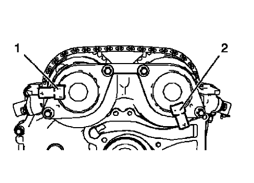
Fig. 427: Camshaft Position Actuator Solenoid Valves Proper Position
- The 2 camshaft position actuator solenoid valves should be installed in the position as shown (1) and (2).
CAMSHAFT COVER INSTALLATION
- Clean the sealing surfaces.
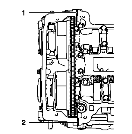
Fig. 428: Sealing Compound Application Areas
NOTE: The thickness of the sealing bead should be 2 mm (0.0787 in).
- Apply sealing compound to areas (1) and (2). Refer to Adhesives, Fluids, Lubricants, and Sealers.
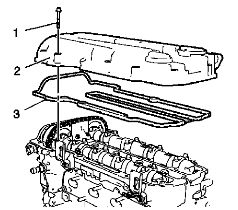
Fig. 429: Camshaft Cover And Gasket
NOTE: The installation procedure should not take longer than 10 minutes.
- Install the camshaft cover (2) and a NEW gasket (3).
- Install the 15 camshaft cover bolts (1).
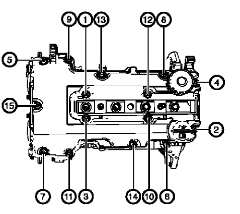
Fig. 430: Camshaft Cover Bolts Tightening Sequence
- Tighten the 15 camshaft cover bolts in a sequence as shown to 8 N.m (71 lb in).
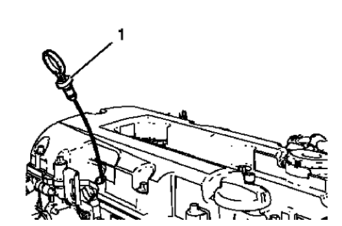
Fig. 431: Engine Oil Level Indicator
- Install the oil level indicator (1).
IGNITION COIL INSTALLATION
Special Tools
EN-6009 Remover and Installer Ignition Module
For equivalent regional tools, refer to Special Tools.
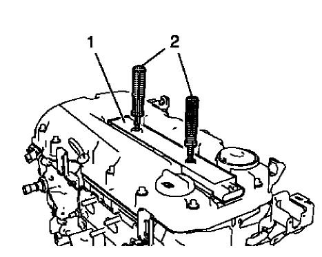
Fig. 432: Ignition Coil And Remover/Installer
- Install the ignition coil (1) and remove EN-6009 remover and installer (2).
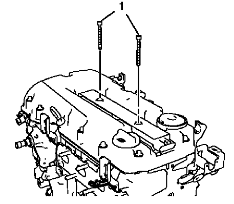
Fig. 433: Ignition Coil Bolts
CAUTION: Refer to Fastener Caution .
- Install the 2 ignition coil bolts (1) and tighten to 8 N.m (71 lb in).
ENGINE FLYWHEEL INSTALLATION
Special Tools
- EN-470-B Angular Torque Wrench
- EN-652 Flywheel Holder
For equivalent regional tools, refer to Special Tools.
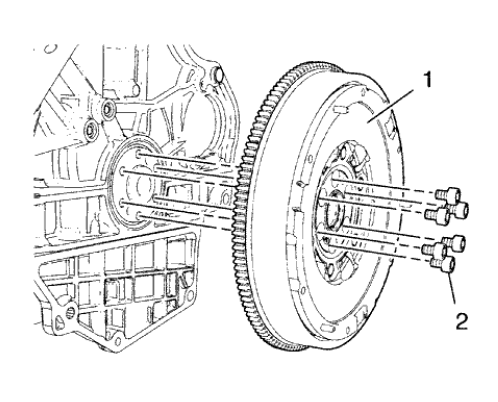
Fig. 434: Engine Flywheel And Bolts
- Install the engine flywheel (1).
- Install the 6 NEW engine flywheel bolts (2).
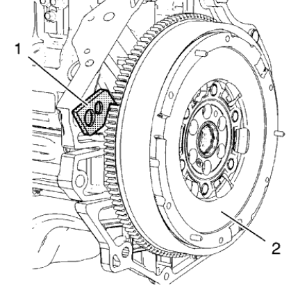
Fig. 435: Engine Flywheel And Holder
- Install EN-652 holder (1) to hold the engine flywheel (2).
CAUTION: Refer to Fastener Caution .
CAUTION: Refer to Torque-to-Yield Fastener Caution .
- Tighten the 6 engine flywheel bolts in a cross sequence to 60 N.m (44 lb ft).
- Tighten the 6 engine flywheel bolts in a cross sequence to an additional 45 degrees. Use EN-470-B wrench.
- Tighten the 6 engine flywheel bolts in a cross sequence to an additional 15 degrees. Use EN-470-B wrench.
- Remove EN-652 holder.
GENERATOR INSTALLATION
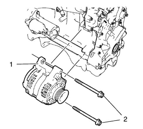
Fig. 436: Generator And Bolts
- Install the generator (1).
CAUTION: Refer to Fastener Caution .
- Install the 2 generator bolts (2) and tighten to 35 N.m (26 lb ft)
Starter installation
.gif)
Fig. 437: Starter, Bolt, Stud And Washer
- Install the starter (4).
- Install the lower starter bolt stud (3) and if equipped the washer.
- Install the upper starter bolt (2) and if equipped the washer (1).
CAUTION: Refer to Fastener Caution .
- Tighten the starter bolt and starter bolt stud to 25 N.m (18 lb ft).
INTAKE MANIFOLD INSTALLATION
- Clean the sealing surfaces.
.gif)
Fig. 438: Intake Manifold
- Install the intake manifold (1) along with a NEW intake manifold gasket.
.gif)
Fig. 439: Intake Manifold Bolts
CAUTION: Refer to Fastener Caution .
- Install the 6 intake manifold bolts (1) and tighten to 20 N.m (15 lb ft).
THROTTLE BODY INSTALLATION
.gif)
Fig. 440: Throttle Body And Bolts
- Install the throttle body (2) and a NEW throttle body seal ring (1).
CAUTION: Refer to Fastener Caution .
- Install the 4 throttle body bolts (3) and tighten to 8 N.m (71 lb in).
WATER PUMP INSTALLATION
Special Tools
EN-45059 Angle Meter
For equivalent regional tools, refer to Special Tools.
- Clean the sealing surfaces.
.gif)
Fig. 441: Water Pump And Engine Front Cover Bolts
- The water pump and engine front cover bolts are located as followed:
- Engine front cover special bolt without cone end 60 mm (2.362 in) (1).
- Engine front cover standard bolt with cone end 52 mm (2.047 in) (2).
- Water pump bolt 25 mm (0.984 in) (3).
.gif)
Fig. 442: Water Pump, Bolts And Gasket
- Install the water pump (2) and a NEW water pump gasket (1).
CAUTION: Refer to Fastener Caution .
- Install the 5 water pump bolts (4) and the 5 long engine front cover bolts (3) and tighten in a cross sequence to 8 (71 lb in).
.gif)
Fig. 443: Identifying Water Pump Bolts
CAUTION: Refer to Torque-to-Yield Fastener Caution .
- Tighten the 2 water pump bolts (1) to an additional 30 degrees, using the EN-45059 meter
CRANKSHAFT BALANCER INSTALLATION
Special Tools
- EN-470-B Angular Torque Wrench
- EN-956-1 Extension
- EN-49979 Crankshaft Shock Mount Retainer
For equivalent regional tools, refer to Special Tools.
.gif)
Fig. 444: Engine Oil Pump Rotor And Crankshaft
NOTE: The crankshaft balancer flange must fit to the hexagon of the oil pump rotor (2) and to the two-flat of the crankshaft (1).
- Install the crankshaft balancer by carefully pressing into position.
.gif)
Fig. 445: Engine Front Cover And Crankshaft Balancer
- Measure the distance a between the crankshaft balancer (2) and the engine front cover (1). The distance a should be 5.5 mm (0.21654 in).
NOTE: Never re-use the crankshaft balancer bolt.
- Install a NEW crankshaft balancer bolt.
.gif)
Fig. 446: Crankshaft Balancer, Retainer And Extension
CAUTION: Refer to Fastener Caution .
CAUTION: Refer to Torque-to-Yield Fastener Caution .
- Tighten the crankshaft balancer bolt (4) while holding the crankshaft balancer (3) with EN-49979 retainer (1) and EN-956-1 extension (2) in the following order:
- Tighten the crankshaft balancer bolt to 150 N.m (111 lb ft).
- Tighten the crankshaft balancer bolt to an additional 45 degrees, using EN-470-B wrench.
WATER PUMP PULLEY INSTALLATION
.gif)
Fig. 447: Water Pump Pulley
- Install the water pump pulley (1).
- Install the 3 water pump pulley bolts (2).
CAUTION: Refer to Fastener Caution .
- Tighten the 3 water pump pulley bolts (2) to 22 N.m (16 lb ft) while holding up the water pump pulley hub with a wrench.
AIR CONDITIONING COMPRESSOR BRACKET INSTALLATION
.gif)
Fig. 448: Power Steering Pump Bracket/Air Conditioning Compressor Bracket And
Bolts
- Install the air conditioning compressor bracket (2).
CAUTION: Refer to Fastener Caution
- Install the 3 air conditioning compressor bracket bolts (1) and tighten to 22 N.m (16 lb ft).
DRIVE BELT TENSIONER INSTALLATION
.gif)
Fig. 449: Drive Belt Tensioner And Bolts
- Install the drive belt tensioner (1).
- Install the upper drive belt tensioner bolt (2).
- Install the lower drive belt tensioner bolt (3).
CAUTION: Refer to Fastener Caution .
- Tighten the lower drive belt tensioner bolt (M8) to 22 N.m (16 lb ft).
- Tighten the upper drive belt tensioner bolt to 55 N.m (41 lb ft).
Drive belt installation
Special Tools
- EN-955 Locking Pins
- EN-48488 Holding Wrench
For equivalent regional tools, refer to Special Tools.
NOTE: Ensure that the drive belt tensioner is held with EN-955-2 locking pin.
- Install the drive belt.
.gif)
Fig. 450: Locking Pin And Wrench
- Move the drive belt tensioner clockwise until EN-955-20 locking pin (2) can be removed. Use EN-48488 wrench (1).
- Remove EN-955-20 locking pin (2) from the drive belt tensioner while holding with EN-48488 wrench (1).
- Release tension from drive belt tensioner and remove EN-48488 wrench (1).
ENGINE OIL COOLER INSTALLATION
.gif)
Fig. 451: Locating Engine Oil Cooler Components
NOTE: Lubricate the oil cooler seal (8) with clean engine oil.
- Install the engine oil cooler assembly (6) along with 2 NEW sealings (8) and (9).
- Install the 3 oil cooler bolts (5) and tighten to 10 N.m (89 lb in).
- Install the oil cooler coolant outlet pipe bolt (7) and tighten to 10 N.m (89 lb in).
- Install the oil cooler coolant outlet hose (2) to the engine coolant thermostat housing.
- Install the oil cooler coolant outlet hose clamp (1).
- Install the oil cooler coolant inlet hose (4) to the water outlet.
- Install the oil cooler coolant inlet hose clamp (3).
WATER OUTLET INSTALLATION
- Clean the sealing surfaces.
.gif)
Fig. 452: Water Outlet, Bolts And Seal Ring
- Install the water outlet (2) and a NEW water outlet seal ring (1).
CAUTION: Refer to Fastener Caution .
- Install the 3 water outlet bolts (3) and tighten to 8 N.m (71 lb in).
ENGINE COOLANT THERMOSTAT HOUSING INSTALLATION
- Clean the sealing surfaces.
.gif)
Fig. 453: Engine Coolant Thermostat Housing
- Install the engine coolant thermostat housing (2) and a NEW engine coolant thermostat housing seal ring (3).
CAUTION: Refer to Fastener Caution .
- Install the 3 engine coolant thermostat housing bolts (1) and tighten to 8 N.m (71 lb in).
TURBOCHARGER INSTALLATION
Special Tool
EN-49942 Holding Wrench
For equivalent regional tools, refer to Special Tools.
- Clean the sealing surfaces.
- Replace the connect fittings on the turbocharger coolant feed pipe and the turbocharger coolant return pipe. Refer to Turbocharger Disassemble, and Turbocharger Assemble.
.gif)
Fig. 454: Turbocharger Assembly And Turbocharger Gasket
NOTE: Mind the turbocharger oil return pipe.
- Install the turbocharger assembly (1) and a NEW turbocharger gasket (2).
.gif)
Fig. 455: Turbocharger Oil Return Pipe
- Connect the turbocharger oil return pipe to the engine while installing the turbocharger.
- Install the turbocharger coolant feed pipe hollow screw along with 2 NEW seal rings (1) and (2).
.gif)
Fig. 456: Turbocharger Nuts
- Install the 8 NEW turbocharger nuts (1).
.gif)
Fig. 457: Turbocharger Nuts Tightening Sequence
CAUTION: Refer to Fastener Caution .
CAUTION: Refer to Torque-to-Yield Fastener Caution .
- Tighten the 8 turbocharger nuts in a sequence as shown to 8 (71 lb in).
- Repeat the tightening procedure to ensure a proper fastening of the turbocharger nuts.
.gif)
Fig. 458: Turbocharger Oil Feed Pipe Components
- Connect the turbocharger coolant return hose (6) to the oil cooler coolant inlet pipe and install the turbocharger coolant return pipe bolt (7) to the oil cooler. Tighten the turbocharger coolant return pipe bolt to 8 (71 lb in).
- Install the turbocharger oil feed pipe (2) along with a NEW rubber seal ring.
- Install the turbocharger oil feed pipe hollow screw (4) in compound with 2 NEW seal rings (1) and (3).
- Install the turbocharger oil feed pipe bolt (5) to the oil cooler and tighten to 8 (71 lb in).
- Tighten the turbocharger oil feed pipe hollow screw to 20 (15 lb ft).
.gif)
Fig. 459: Holding Wrench And Ratchet Wrench
NOTE: The EN-49942 holding wrench (2) should be installed to turbocharger coolant feed pipe as shown. The holding wrench should be installed to avoid twisting of the turbocharger coolant feed pipe during the fastening procedure.
- Install the EN-49942 holding wrench (2) to the turbocharger coolant feed pipe. Guide a ratchet wrench (1) along with an extension through EN-49942 holding wrench to the turbocharger coolant feed pipe hollow screw.
.gif)
Fig. 460: Ratchet Wrench, Holding Wrench And Coolant Feed Pipe
NOTE: EN-49942 holding wrench (2) should be installed to turbocharger coolant feed pipe as shown. The holding wrench should be installed to avoid twist of the turbocharger coolant feed pipe while the fastening procedure.
- Tighten the turbocharger coolant feed pipe hollow screw with ratchet wrench and extension (1) to 30 (22 lb ft).
EXHAUST MANIFOLD HEAT SHIELD INSTALLATION
.gif)
Fig. 461: Exhaust Manifold Heat Shield
- Install the exhaust manifold heat shield (2).
CAUTION: Refer to Fastener Caution .
- Install the 3 exhaust manifold heat shield bolts (1) and the washers and tighten to 8 N.m (71 lb in).
WARM UP THREE-WAY CATALYTIC CONVERTER INSTALLATION
.gif)
Fig. 462: Locating Catalytic Converter Components
- Install the warm up three way catalytic converter (5) to the brackets and the turbocharger. Use a NEW warm up three way catalytic converter seal (2).
NOTE: Never re-use the V-clamp.
- Install a NEW warm up three way catalytic converter V-clamp (1).
- Install the 2 catalytic converter to catalytic converter bracket nuts (4) and (6) and hand tighten.
- Hand tighten the catalytic converter V-clamp.
- Connect the heated oxygen sensor wiring harness (3) to retainer clip.
.gif)
Fig. 463: Catalytic Converter V-Clamp
- The catalytic converter V-clamp (1) should be installed in the shown position.
CAUTION: Refer to Fastener Caution .
- Tighten the catalytic converter to catalytic converter bracket nuts to 22 N.m (16 lb ft).
- Tighten the catalytic converter V-clamp to 13 N.m (115 lb in).
Positive crankcase ventilation pipe installation
.gif)
Fig. 464: Turbocharger, Positive Crankcase Ventilation Pipe Assembly And
Charger Air Bypass Valve Pipe
- Install the positive crankcase ventilation pipe assembly (1) to the camshaft cover retainer clips.
- Connect the positive crankcase ventilation pipe to turbocharger (3).
- Install the charger air bypass valve pipe (2) to turbo charger waste regulator solenoid valve.
- Install the charger air bypass valve pipe to turbocharger.
- Fasten the charger air bypass valve pipe clamp (4).
.gif)
Fig. 465: Positive Crankcase Ventilation Pipe Retainer Clips And Retainer
Clamp
- Install the positive crankcase ventilation pipe to the intake manifold and fix with retainer clamp (1).
- Clip in the positive crankcase ventilation pipe to the 2 retainer clips (2) and (3).
ENGINE MOUNT BRACKET INSTALLATION
.gif)
Fig. 466: Engine Mount Bracket And Bolts
- Install the engine mount bracket (2).
CAUTION: Refer to Fastener Caution .
- Install the 3 engine mount bracket bolts and tighten to 60 N.m (45 lb ft) + 45-60º.
ENGINE FRONT COVER AND OIL PUMP ASSEMBLE
Oil Pump Installation
.gif)
Fig. 467: Oil Pump Components
NOTE: The oil pump slide spring and pin, as well as the slide seal and slide seal spring can be ordered as single parts. All other oil pump components can only be ordered as a replacement kit.
- Install the oil pump components in the following order:
NOTE: The bore (8) in the oil pump slide must fit smooth-running and without clearance to the oil pump slide pivot pin (7).
- Install the oil pump slide (6).
- Install the inner oil pump vane ring (5).
NOTE: Mind the installation position of the oil pump vane rotor (4). The mark (9) must point to direction of the oil pump cover.
- Install the oil pump vane rotor (4).
NOTE: Mind the localized flats (3) on the oil pump vanes (2) caused by the oil pump vane rings. The localized flats must point to the oil pump vane rotor.
- Install the 6 oil pump vanes (2).
- Install the outer oil pump vane ring (1).
.gif)
Fig. 468: Oil Pump Slide Seal Springs And Grooves
- Install the 2 oil pump slide seals and the 2 oil pump slide seal springs (2) in the position as shown to the 2 grooves (1) of the oil pump slide.
.gif)
Fig. 469: Oil Pump Slide Spring, Pin, Chambers And Front Cover Edge
- Protect the engine front cover edge (5) with a suitable piece of plastic.
NOTE: The length of the removed oil pump slide spring (2) should be 76.5 mm (3.0118 in) for suction engines and 61 mm (2.4016 in) for turbo engines.
- Install the oil pump slide spring pin along with the oil pump slide spring (4). Use a screwdriver to compress the oil pump slide spring. The flat side of oil pump slide spring pin must face upwards.
- Measure the oil pump clearances to ensure a correct installation of the oil pump components. Refer to Engine Front Cover and Oil Pump Cleaning and Inspection.
- Lubricate the oil pump vanes, the oil pump vane rotor, the oil pump slide spring and the area (3) with engine oil.
- Inspect the oil pump slide spring mechanism for functionality.
.gif)
Fig. 470: Engine Oil Pump Cover And Bolts
- Install the oil pump cover (2) and the 8 oil pump cover bolts (1).
.gif)
Fig. 471: Oil Pump Cover Bolts Tightening Sequence
CAUTION: Refer to Fastener Caution .
- Tighten the oil pump cover bolts in a sequence as shown to 8 N.m (71 lb in).
.gif)
Fig. 472: Crankshaft Balancer
- Install the crankshaft balancer (1) and rotate in the direction shown (2) in order to inspect the function of the oil pump mechanism. The crankshaft balancer should rotate easily.
Engine Front Cover Assemble
.gif)
Fig. 473: Locating Engine Front Cover Components
- Install the crankshaft front oil seal (10).
- Install the oil pressure relief valve (7), (8) and (9) and tighten to 50 N.m (37 lb ft).
- Install the exhaust camshaft position sensor (5) and the seal ring (4).
- Install the exhaust camshaft sensor bolt (6) and tighten to 6 N.m (53 lb in).
- Install the intake camshaft position sensor (2) and the seal ring (3).
- Install the intake camshaft sensor bolt (1) and tighten to 6 N.m (53 lb in).
Drive belt removal
Special Tools
- EN-955 Locking Pins
- EN-48488 Holding Wrench
For equivalent regional tools, refer to Special Tools.
.gif)
Fig. 474: Locking Pin And Wrench
- Install EN-48488 wrench (1) to the drive belt tensioner.
NOTE: The drive belt tensioner must always be in a pre-tensioned state.
- Move the drive belt tensioner clockwise until the drive belt tensioner can be fixed with the EN-955-20 locking pin (2).
- Remove the drive belt.
AUTOMATIC TRANSMISSION FLEX PLATE REMOVAL
Special Tools
EN-652 Flywheel Holder
For equivalent regional tools, refer to Special Tools.
.gif)
Fig. 475: Automatic Transmission Flex Plate
- Install the EN-652 flywheel holder (1) in order to fix the automatic transmission flex plate (2).
.gif)
Fig. 476: Automatic Transmission Flex Plate And Bolts
- Remove and DISCARD the 6 automatic transmission flex plate bolts (2).
- Remove the automatic transmission flex plate (1).
ENGINE BLOCK CLEANING AND INSPECTION
Special Tools
EN-8087 Cylinder Bore Gauge
For equivalent regional tool, refer to Special Tools.
Cleaning Procedure
- Remove any old thread sealant, gasket material or sealant.
- Clean all the following areas with solvent:
- Sealing surfaces
- Cooling passages
- Oil passages
- Clean all threaded and through holes with solvent.
WARNING: Wear safety glasses when using compressed air in order to prevent eye injury.
- Dry the engine block with compressed air.
Visual Inspection
- Inspect the crankshaft bearings journals for damage or spun bearings. The crankshaft bearing journals are not repairable, if the crankshaft bearing journals are damaged the engine block assembly must be replaced.
- Inspect all sealing and mating surfaces for damage, repair or replace the engine block assembly if necessary.
- Inspect all threaded and through holes for damage or excessive debris.
- Inspect all bolts for damage, if damaged replace with NEW bolts only.
- Inspect the cylinder walls for cracks or damage. The cylinder sleeves are not serviced separately, if the cylinders are damaged the cylinder block assembly must be replaced.
- Inspect the engine block for cracks. Do not repair any cracks. If cracks are found, the cylinder block assembly must be replaced.
Measuring Procedure
Engine Block Flatness Inspection
.gif)
Fig. 477: Inspecting Engine Block For Distortion Using Straight Edge
- Inspect the engine block as shown for distortion. Use a straightedge (1).
.gif)
Fig. 478: Inspecting Engine Block For Deflection Using Straight Edge
- Inspect the engine block as shown for deflection. Use a straightedge (1).
Cylinder bore and crankshaft bearing bore
NOTE: Old bolts can be used for the measuring procedure.
- Install the crankshaft bearing cap tie plate and tighten.
.gif)
Fig. 479: Measuring Bearing Bore Concentricity And Alignment Using Gauge Tool
- Inspect the crankshaft main bearing bores. Use the EN-8087 gauge (1) to measure the bearing bore concentricity and alignment. Refer to Engine Mechanical Specifications to find the permitted values.
- Replace the engine block and crankshaft bearing cap tie plate if the crankshaft bearing bores are out of specification.
.gif)
Fig. 480: Inspecting Cylinder Bore
- Inspect the cylinder bores using the EN-8087 gauge (1). Inspect for the following items:
- Wear
- Taper
- Runout
- Ridging
- Refer to Engine Mechanical Specifications to find the permitted values.
- If the cylinder bores are out of specification, replace the engine block.
- Remove the crankshaft bearing cap tie plate.
AUTOMATIC TRANSMISSION FLEX PLATE INSTALLATION
Special Tools
EN-652 Flywheel Holder
For equivalent regional tools, refer to Special Tools
- Clean the 6 screw bores. Rework if necessary.
.gif)
Fig. 481: Automatic Transmission Flex Plate And Bolts
- Install the automatic transmission flex plate (1).
- Install 6 NEW automatic transmission flex plate bolts (2).
.gif)
Fig. 482: Automatic Transmission Flex Plate
- Install EN-652 flywheel holder (1) in order to fix the automatic transmission flex plate (2).
CAUTION: Refer to Fastener Caution .
CAUTION: Refer to Torque-to-Yield Fastener Caution .
- Tighten the 6 automatic transmission flex plate bolts in a cross sequence to 35 N.m(26 lb ft).
- Tighten the 6 automatic transmission flex plate bolts in a cross sequence to an additional 30º.
- Tighten the 6 automatic transmission flex plate bolts in a cross sequence to an additional 15º.

