Buick Encore: Seat Heating and Cooling - Diagnostic information and procedures
DTC B1925 OR B2170 (without memory A45): Seat cushion heater sensor
SCHEMATIC WIRING DIAGRAMS
HEATED/COOLED SEAT WIRING SCHEMATICS (ENCORE)
KA1
Fig. 1: KA1
HEATED/COOLED SEAT WIRING SCHEMATICS (Encore)
KA1
Fig. 2: KA1
DIAGNOSTIC INFORMATION AND PROCEDURES
DTC B1925 OR B2170 (WITHOUT MEMORY A45): SEAT CUSHION HEATER SENSOR
DIAGNOSTIC CODE INDEX
Diagnostic Instructions
- Perform the Diagnostic System Check - Vehicle prior to using this diagnostic procedure.
- Review Strategy Based Diagnosis for an overview of the diagnostic approach.
- Diagnostic Procedure Instructions provides an overview of each diagnostic category.
DTC Descriptors
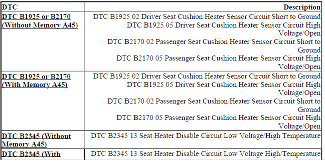
DTC B1925 02
Driver Seat Cushion Heater Sensor Circuit Short to Ground
DTC B1925 05
Driver Seat Cushion Heater Sensor Circuit High Voltage/Open
DTC B2170 02
Passenger Seat Cushion Heater Sensor Circuit Short to Ground
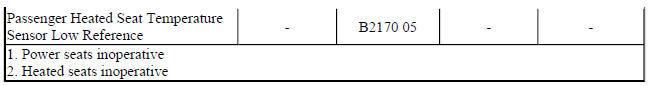
DTC B2170 05
Passenger Seat Cushion Heater Sensor Circuit High Voltage/Open
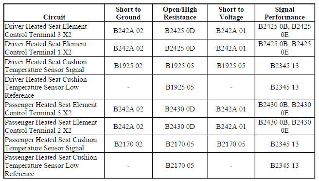
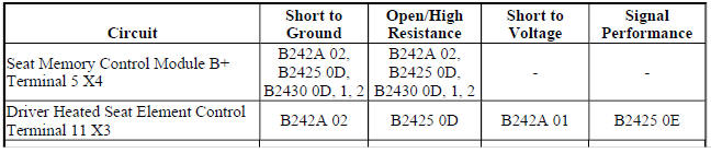
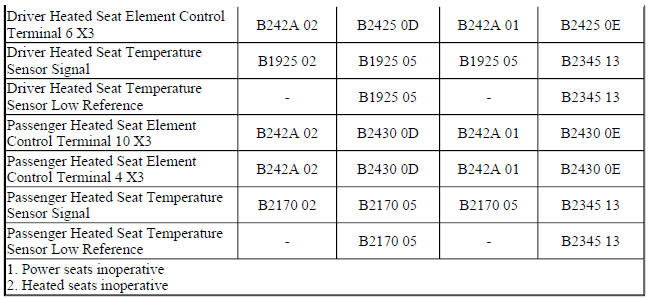
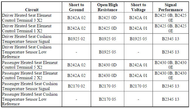
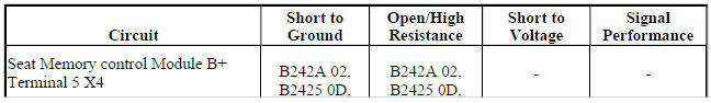
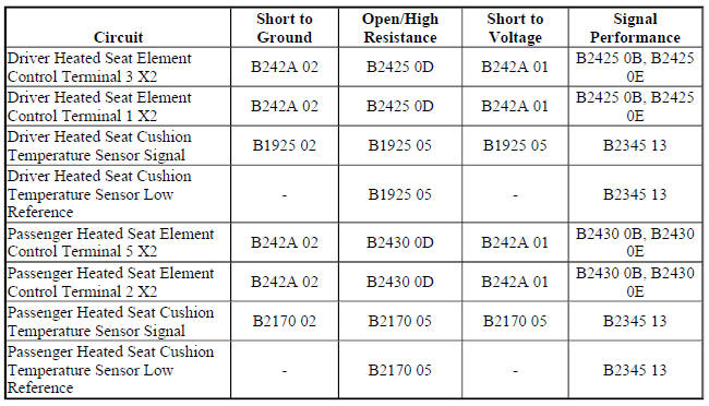
Diagnostic Fault Information
Circuit/System Description
The heated seat temperature sensor is located in the seat cushion just under the seat cover with the seat heating element. The seat heating control module supplies a 5 V reference voltage through the temperature sensor signal circuit and a ground through the low reference circuit to the sensor. The module monitors the voltage of the sensor signal circuit to determine the temperature of the seat. The temperature sensor varies in resistance based on the temperature of the heating element causing the signal voltage to change. Once the seat reaches the set temperature, the module will then cycle the control circuit of the heating elements ON and OFF in order to maintain the desired seat temperature based on the feedback voltage from the sensor.
Conditions for Running the DTC
- DTC B1325 must not be present.
- The seat heating control module must be powered.
Conditions for Setting the DTC
B1925 02 or B2170 02
The temperature sensor voltage drops below 0.6 V for more than 1 s.
B1925 05 or B2170 05
The temperature sensor voltage is greater than 5 V for more than 1 s.
Action Taken When the DTC Sets
The heated seat function for the affected seat will be disabled.
Conditions for Clearing the DTC
- The current DTC will clear and set the code to history 3 s after the reference voltage returns to normal operating range and the ignition is cycled OFF then back to ACC or RUN.
- The history DTC will clear after 40 consecutive fault-free ignition cycles have occurred.
Reference Information
Schematic Reference
Heated/Cooled Seat Schematics (Encore), Heated/Cooled Seat Schematics (Encore)
Connector End View Reference
WIRING SYSTEMS AND POWER MANAGEMENT - COMPONENT CONNECTOR END VIEWS - INDEX - ENCORE WIRING SYSTEMS AND POWER MANAGEMENT - COMPONENT CONNECTOR END VIEWS - INDEX - Encore
Description and Operation
Heated Seats Description and Operation
Electrical Information Reference
- Circuit Testing
- Connector Repairs
- Testing for Intermittent Conditions and Poor Connections
- Wiring Repairs
Scan Tool Reference
Control Module References for scan tool information
Circuit/System Testing
- Ignition OFF and all vehicle systems OFF, disconnect the harness connector at the appropriate E14 Seat Heating Element - Cushion. It may take up to 2 min for all vehicle systems to power down.
- Test for less than 10 ohms between the low reference circuit terminal C and ground.
- If 10 ohms or greater
- Ignition OFF, disconnect the X2 harness connector at the K29 Seat Heating Control Module.
- Test for less than 2 ohms in the low reference circuit end to end.
- If 2 ohms or greater, repair the open/high resistance in the circuit.
- If less than 2 ohms, replace the K29 Seat Heating Control Module.
- If less than 10 ohms
- Ignition ON.
- Test for 4.8-5.2 V between the signal circuit terminal B and ground.
- If less than 4.8 V
- Ignition OFF, disconnect the X3 harness connector at the K29 Seat Heating Control Module.
- Test for infinite resistance between the signal circuit and ground.
- If less than infinite resistance, repair the short to ground on the circuit.
- If infinite resistance
- Test for less than 2 ohms in the signal circuit end to end.
- If 2 ohms or greater, repair the open/high resistance in the circuit.
- If less than 2 ohms, replace the K29 Seat Heating Control Module.
- If greater than 5.2 V
- Ignition OFF, disconnect the X3 harness connector at the K29 Seat Heating Control Module, ignition ON.
- Test for less than 1 V between the signal circuit and ground.
- If 1 V or greater, repair the short to voltage on the circuit.
- If less than 1 V, replace the K29 Seat Heating Control Module.
- If between 4.8-5.2 V
- Test or replace the E14 Seat Heating Element - Cushion.
Component Testing
Seat Cushion Heating Element
- Ignition OFF, disconnect the harness connector at the appropriate E14 Seat Heating Element - Cushion.
- Test for 500 ohms-300 kohms between the signal circuit terminal B and the low reference circuit terminal C.
- If not between 500 ohms-300 kohms
Replace the E14 Seat Heating Element - Cushion.
- If between 500 ohms-300 kohms
- All OK.
Repair Instructions
Perform the Diagnostic Repair Verification after completing the repair.
- Driver or Passenger Seat Cushion Heater Replacement
- Control Module References for K29 Seat Heating Control Module replacement, programming and setup
DTC B1925 OR B2170 (With memory A45): Seat cushion heater sensor
Diagnostic Instructions
- Perform the Diagnostic System Check - Vehicle prior to using this diagnostic procedure.
- Review Strategy Based Diagnosis for an overview of the diagnostic approach.
- Diagnostic Procedure Instructions provides an overview of each diagnostic category.
DTC Descriptors
DTC B1925 02
Driver Seat Cushion Heater Sensor Circuit Short to Ground
DTC B1925 05
Driver Seat Cushion Heater Sensor Circuit High Voltage/Open
DTC B2170 02
Passenger Seat Cushion Heater Sensor Circuit Short to Ground
DTC B2170 05
Passenger Seat Cushion Heater Sensor Circuit High Voltage/Open
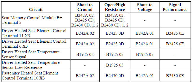
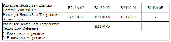
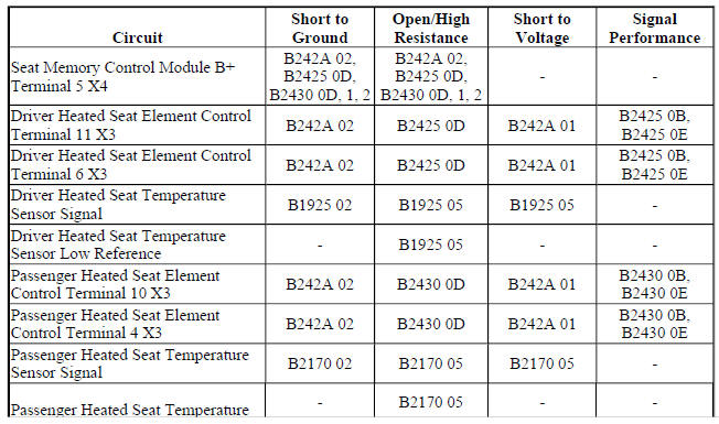
Diagnostic Fault Information
Circuit/System Description
The heated seat temperature sensor is located in the seat cushion just under the seat cover with the seat heating element. The seat memory control module supplies a 5 V reference voltage through the temperature sensor signal circuit and a ground through the low reference circuit to the sensor. The module monitors the voltage of the sensor signal circuit to determine the temperature of the seat. The temperature sensor varies in resistance based on the temperature of the heating element causing the signal voltage to change. Once the seat reaches the set temperature, the module will then cycle the control circuit of the heating elements ON and OFF in order to maintain the desired seat temperature based on the feedback voltage from the sensor.
Conditions for Running the DTC
- DTC B1325 must not be present.
- The seat memory control module must be powered.
Conditions for Setting the DTC
B1925 02 or B2170 02
The temperature sensor voltage drops below 0.6 V for more than 1 s.
B1925 05 or B2170 05
The temperature sensor voltage is greater than 5 V for more than 1 s.
Action Taken When the DTC Sets
The heated seat function for the affected seat will be disabled.
Conditions for Clearing the DTC
- The current DTC will clear and set the code to history 3 s after the reference voltage returns to normal operating range and the ignition is cycled OFF then back to ACC or RUN.
- The history DTC will clear after 40 consecutive fault-free ignition cycles have occurred.
Reference Information
Schematic Reference
Heated/Cooled Seat Schematics (Encore), Heated/Cooled Seat Schematics (Encore)
Connector End View Reference
WIRING SYSTEMS AND POWER MANAGEMENT - COMPONENT CONNECTOR END VIEWS - INDEX - ENCORE WIRING SYSTEMS AND POWER MANAGEMENT - COMPONENT CONNECTOR END VIEWS - INDEX - Encore
Description and Operation
Heated Seats Description and Operation
Electrical Information Reference
- Circuit Testing
- Connector Repairs
- Testing for Intermittent Conditions and Poor Connections
- Wiring Repairs
Scan Tool Reference
Control Module References for scan tool information
Circuit/System Testing
- Ignition OFF and all vehicle systems OFF, disconnect the harness connector at the appropriate E14B or E14D Seat Heating Element - Cushion. It may take up to 2 min for all vehicle systems to power down.
- Test for less than 10 ohms between the low reference circuit terminal C and ground.
- If 10 ohms or greater
- Ignition OFF, disconnect the X3 harness connector at the K40 Seat Memory Control Module.
- Test for less than 2 ohms in the low reference circuit end to end.
- If 2 ohms or greater, repair the open/high resistance in the circuit.
- I less than 2 ohms, replace the K40 Seat Memory Control Module.
- If less than 10 ohms
- Ignition ON.
4. Test for 4.8-5.2 V between the signal circuit terminal B and ground.
If less than 4.8 V
- Ignition OFF, disconnect the X2 harness connector at the K40 Seat Memory Control Module.
- Test for infinite resistance between the signal circuit and ground.
- If less than infinite resistance, repair the short to ground on the circuit.
- If infinite resistance
- Test for less than 2 ohms in the signal circuit end to end.
- If 2 ohms or greater, repair the open/high resistance in the circuit.
- If less than 2 ohms, replace the K40 Seat Memory Control Module.
- If greater than 5.2 V
- Ignition OFF, disconnect the X2 harness connector at the K40 Seat Memory Control Module, ignition ON.
- Test for less than 1 V between the signal circuit and ground.
- If 1 V or greater, repair the short to voltage on the circuit.
- If less than 1 V, replace the K40 Seat Memory Control Module.
- If between 4.8-5.2 V
- Test or replace the E14 Seat Heating Element - Cushion.
Component Testing
Seat Cushion Heating Element
- Ignition OFF, disconnect the harness connector at the appropriate E14B or E14D Seat Heating Element - Cushion.
- Test for 500 ohms-300 kohms between the signal circuit terminal B and the low reference circuit terminal C.
- If not between 500 ohms-300 kohms
Replace the E14 Seat Heating Element - Cushion.
- If between 500 ohms-300 kohms
- All OK.
Repair Instructions
Perform the Diagnostic Repair Verification after completing the repair.
- Driver or Passenger Seat Back Cushion Heater Replacement
- Driver or Passenger Seat Cushion Heater Replacement Control Module References for K40 Seat Memory Control Module replacement, programming and setup
DTC B2345 (WITHOUT MEMORY A45): Seat heater disable circuit low voltage/high temperature
Diagnostic Instructions
- Perform the Diagnostic System Check - Vehicle prior to using this diagnostic procedure.
- Review Strategy Based Diagnosis for an overview of the diagnostic approach.
- Diagnostic Procedure Instructions provides an overview of each diagnostic category
DTC Descriptors
DTC B2345 13
Seat Heater Disable Circuit Low Voltage/High Temperature
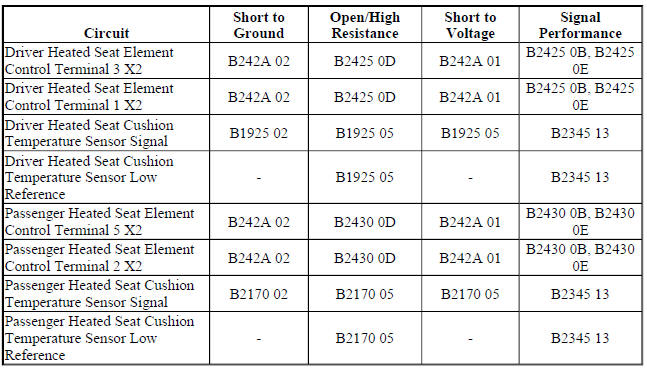
Diagnostic Fault Information
Circuit/System Description
The heated seat temperature sensor is located in the seat cushion just under the seat cover with the seat heating element. The seat heating control module supplies a 5 V reference voltage through the temperature sensor signal circuit and a ground through the low reference circuit to the sensor. The module monitors the voltage of the sensor signal circuit to determine the temperature of the seat. The temperature sensor varies in resistance based on the temperature of the heating element causing the signal voltage to change. Once the seat reaches the set temperature, the module will then cycle the control circuit of the heating elements ON and OFF in order to maintain the desired seat temperature based on the feedback voltage from the sensor.
Conditions for Running the DTC
The seat heating control module must be powered.
Conditions for Setting the DTC
B2345 13
Any temperature sensor input that remains below 1.5 V for more than 1 s.
Action Taken When the DTC Sets
The heated seat function for both seats will be disabled.
Conditions for Clearing the DTC
- The current DTC will clear and set the code to history 3 s after the reference voltage returns to the normal operating range and the ignition is cycled OFF then back to ACC or RUN.
- The history DTC will clear after 40 consecutive fault-free ignition cycles have occurred.
Reference Information
Schematic Reference
Heated/Cooled Seat Schematics (Encore), Heated/Cooled Seat Schematics (Encore)
Connector End View Reference
WIRING SYSTEMS AND POWER MANAGEMENT - COMPONENT CONNECTOR END VIEWS - INDEX - ENCORE WIRING SYSTEMS AND POWER MANAGEMENT - COMPONENT CONNECTOR END VIEWS - INDEX - Encore
Description and Operation
Heated Seats Description and Operation
Electrical Information Reference
- Circuit Testing
- Connector Repairs
- Testing for Intermittent Conditions and Poor Connections
- Wiring Repairs
Scan Tool Reference
Control Module References for scan tool information
Circuit/System Testing
- Ignition OFF, disconnect the X2 and X3 harness connectors at the K29 Seat Heating Control Module
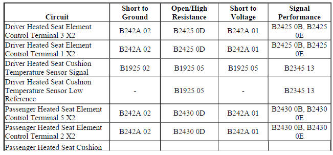
- Test for greater than 3.0 kohms between the signal and the low reference circuit terminals listed below:
- Driver seat cushion terminal 3 X3 and terminal 13 X2
- Passenger seat cushion terminal 4 X3 and terminal 14 X2
- If less than 3.0 kohms
- Ignition OFF, disconnect the harness connector at the appropriate E14 Seat Heating Element - Cushion.
- Test for Infinite resistance between the signal and low reference circuits.
- If less than infinite resistance, repair the short between the circuits.
- If infinite resistance, test or replace the E14 Seat Heating Element - Cushion.
- If greater than 3.0 kohms
- Replace the K29 Seat Heating Control Module.
Repair Instructions
Perform the Diagnostic Repair Verification after completing the repair.
- Driver or Passenger Seat Cushion Heater Replacement
- Control Module References for K29 Seat Heating Control Module replacement, setup and programming
DTC B2345 (WITH MEMORY A45): Seat heater disable circuit low voltage high/temperature
Diagnostic Instructions
- Perform the Diagnostic System Check - Vehicle prior to using this diagnostic procedure.
- Review Strategy Based Diagnosis for an overview of the diagnostic approach.
- Diagnostic Procedure Instructions provides an overview of each diagnostic category.
DTC Descriptors
DTC B2345 13
Seat Heater Disable Circuit Low Voltage High/Temperature
Diagnostic Fault Information
Circuit/System Description
The seat memory control module controls seat heating operation for both the driver and front passenger seats.
The heating elements are controlled through individual high side and low side control circuits. The low side control circuits for both seats are connected to a common reference point internal to the module. This reference point is biased to approximately 2.5 V. Before the seat memory control module will allow heated seat operation, it checks to see if this biased voltage is shorted to ground or voltage. Once the module verifies that it is not closing to a shorted heating element, it allows for heated seat operation. The module will then continue to monitor the heating elements for a shorted circuit.
Conditions for Running the DTC
The seat memory control module must be powered.
Conditions for Setting the DTC
B2345 13
Any temperature sensor input that remains below 1.5 V for more than 1 s.
Action Taken When the DTC Sets
The heated seat function for both front seats will be disabled.
Conditions for Clearing the DTC
- The current DTC will clear and set the code to history 3 s after the reference voltage returns to the normal operating range and the ignition is cycled OFF then back to ACC or RUN.
- The history DTC will clear after 40 consecutive fault-free ignition cycles have occurred.
Reference Information
Schematic Reference
Heated/Cooled Seat Schematics (Encore), Heated/Cooled Seat Schematics (Encore)
Connector End View Reference
WIRING SYSTEMS AND POWER MANAGEMENT - COMPONENT CONNECTOR END VIEWS - INDEX - ENCORE WIRING SYSTEMS AND POWER MANAGEMENT - COMPONENT CONNECTOR END VIEWS - INDEX - Encore
Description and Operation
Heated Seats Description and Operation
Electrical Information Reference
- Circuit Testing
- Connector Repairs
- Testing for Intermittent Conditions and Poor Connections
- Wiring Repairs
Scan Tool Reference
Control Module References for scan tool information
Circuit/System Testing
- Ignition OFF, disconnect the X2 and X3 harness connectors at the K40 Seat Memory Control Module.
- Test for greater than 3.0 kohms between the signal and the low reference circuits listed below:
- E14B driver seat cushion terminal 16 X2 and terminal 12 X3
- E14D passenger seat cushion terminal 7 X2 and terminal 1 X3
- If less than 3.0 kohms
- Ignition OFF, disconnect the harness connector at the appropriate E14B or E14D Seat Heating Element - Cushion.
- Test for Infinite resistance between the signal and low reference circuits.
- If less than infinite resistance, repair the short between the circuits.
- If infinite resistance, test or replace the E14 Seat Heating Element - Cushion.
- If greater than 3.0 kohms
- Replace the K40 Seat Memory Control Module.
Component Testing
Seat Cushion Heating Element
- Ignition OFF, disconnect the harness connector at the appropriate E14B or E14D Seat Heating Element - Cushion.
- Test for 500 ohms-300 kohms between the signal circuit terminal B and the low reference circuit terminal C.
- If not between 500 ohms-300 kohms
Replace the E14 Seat Heating Element - Cushion.
- If between 500 ohms-300 kohms
- All OK.
Repair Instructions
Perform the Diagnostic Repair Verification after completing the repair.
- Driver or Passenger Seat Cushion Heater Replacement
- Control Module References for K40 Seat Memory Control Module replacement, programming and setup
DTC B2425 OR B2430 (WITHOUT MEMORY A45): Seat cushion heater circuit
Diagnostic Instructions
- Perform the Diagnostic System Check - Vehicle prior to using this diagnostic procedure.
- Review Strategy Based Diagnosis for an overview of the diagnostic approach.
- Diagnostic Procedure Instructions provides an overview of each diagnostic category.
DTC Descriptors
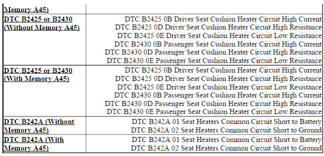
DTC B2425 0B
Driver Seat Cushion Heater Circuit High Current
DTC B2425 0D
Driver Seat Cushion Heater Circuit High Resistance
DTC B2425 0E
Driver Seat Cushion Heater Circuit Low Resistance
DTC B2430 0B
Passenger Seat Cushion Heater Circuit High Current
DTC B2430 0D
Passenger Seat Cushion Heater Circuit High Resistance
DTC B2430 0E
Passenger Seat Cushion Heater Circuit Low Resistance
Diagnostic Fault Information
Circuit/System Description
The driver and front passenger heated seats are controlled by the seat heating control module that is located under the driver seat cushion. When the heated seat is active, the module applies power through a common voltage supply circuit to the seat heater elements. The module controls the seat temperature by providing a pulse width modulation (PWM) ground through the seat heater element control circuit to the heater element. The module then monitors the current flow through the heating element and the rate of change of the temperature sensor to verify correct heated seat operation.
Conditions for Running the DTC
- DTC B1325 must not be present.
- Engine must be ON.
- The seat heating control module must be powered and the heated seat must be enabled.
Conditions for Setting the DTC
B2425 0D or B2430 0D
By measuring current and voltage output to the seat heating element every 10 s, the seat heating control module calculates that the heating element resistance is above the maximum resistance.
B2425 0B, B2425 0E, B2430 0B, or B2430 0E
By measuring current and voltage output to the seat heating element every 10 s, the seat heating control module calculates that the heating element resistance is below the minimum resistance.
Action Taken When the DTC Sets
The heated seat function for the affected seat will be disabled.
Conditions for Clearing the DTC
- The current DTC clears when the malfunction is no longer present, and the power mode changes to OFF then back to ACC or RUN.
- The history DTC will clear after 40 consecutive fault-free ignition cycles have occurred.
Reference Information
Schematic Reference
Heated/Cooled Seat Schematics (Encore), Heated/Cooled Seat Schematics (Encore)
Connector End View Reference
WIRING SYSTEMS AND POWER MANAGEMENT - COMPONENT CONNECTOR END VIEWS - INDEX - ENCORE WIRING SYSTEMS AND POWER MANAGEMENT - COMPONENT CONNECTOR END VIEWS - INDEX - Encore
Description and Operation
Heated Seats Description and Operation
Electrical Information Reference
- Circuit Testing
- Connector Repairs
- Testing for Intermittent Conditions and Poor Connections
- Wiring Repairs
Scan Tool Reference
Control Module References for scan tool information
Circuit/System Testing
B2425 0B, B2425 0D, or B2425 0E
- Ignition OFF, disconnect the harness connector at the E14A Seat Heating Element - Driver Back.
NOTE: Element resistance must be measured twice to ensure that all failure conditions are simulated. First with the seat unoccupied, then with the seat occupied.
- Test for 0.5-2.0 ohms between control circuit terminal A and control circuit terminal B.
- If not between 0.5-2.0 ohms
Replace the E14A Seat Heating Element - Driver Back.
- If between 0.5-2.0 ohms
- Connect the harness connector at the E14A Seat Heating Element - Driver Back and disconnect the X2 harness connector at the K29 Seat Heating Control Module.
NOTE:
Element resistance must be measured twice to ensure that all failure conditions are simulated. First with the seat unoccupied, then with the seat occupied.
- Test for 1-5 ohms between control circuit terminal 3 and control circuit terminal 1.
- If less than 1 ohms
- Ignition OFF, disconnect the harness connector at the E14B Seat Heating Element - Driver Cushion.
- Test for infinite resistance between the control circuits.
- If less than infinite resistance, repair the short between the circuits.
- If infinite resistance, test or replace the E14B Seat Heating Element - Driver Cushion.
- If greater than 5 ohms
- Ignition OFF, disconnect the harness connector at the E14B Seat Heating Element - Driver Cushion.
- Test for less than 2 ohms in each control circuit end to end.
- If 2 ohms or greater, repair the open/high resistance in the circuit
- If less than 2 ohms, test or replace the E14B Seat Heating Element - Driver Cushion.
- If between 1-5 ohms
- Replace the K29 Seat Heating Control Module.
B2430 0B, B2430 0D, or B2430 0E
- Ignition OFF, disconnect the harness connector at the E14C Seat Heating Element - Passenger Back.
NOTE: Element resistance must be measured twice to ensure that all failure conditions are simulated. First with the seat unoccupied, then with the seat occupied.
- Test for 0.5-2.0 ohms between control circuit terminal A and control circuit terminal B.
- If not between 0.5-2.0 ohms
Replace the E14C Seat Heating Element - Passenger Back.
- If between 0.5-2.0 ohms
- Connect the harness connector at the E14C Seat Heating Element - Passenger Back and disconnect the X2 harness connector at the K29 Seat Heating Control Module.
NOTE:
Element resistance must be measured twice to ensure that all failure conditions are simulated. First with the seat unoccupied, then with the seat occupied.
- Test for 1-5 ohms between control circuit terminal 5 and control circuit terminal 2.
- If less than 1 ohms
- Ignition OFF, disconnect the harness connector at the E14D Seat Heating Element - Passenger Cushion.
- Test for infinite resistance between the control circuits.
- If less than infinite resistance, repair the short between the circuits.
- If infinite resistance, test or replace the E14D Seat Heating Element - Passenger Cushion.
- If greater than 5 ohms
- Ignition OFF, disconnect the harness connector at the E14D Seat Heating Element - Passenger Cushion.
- Test for less than 2 ohms in each control circuit end to end.
- If 2 ohms or greater, repair the open/high resistance in the circuit.
- If less than 2 ohms, test or replace the E14D Seat Heating Element - Passenger Cushion.
- If between 1-5 ohms
- Replace the K29 Seat Heating Control Module.
Repair Instructions
Perform the Diagnostic Repair Verification after completing the repair.
- Driver or Passenger Seat Cushion Heater Replacement
- Control Module References for K29 Seat Heating Control Module replacement, programming and setup
DTC B2425 OR B2430 (WITH MEMORY A45): Seat cushion heater circuit
Diagnostic Instructions
- Perform the Diagnostic System Check - Vehicle prior to using this diagnostic procedure.
- Review Strategy Based Diagnosis for an overview of the diagnostic approach.
- Diagnostic Procedure Instructions provides an overview of each diagnostic category
DTC Descriptors
DTC B2425 0B
Driver Seat Cushion Heater Circuit High Current
DTC B2425 0D
Driver Seat Cushion Heater Circuit High Resistance
DTC B2425 0E
Driver Seat Cushion Heater Circuit Low Resistance
DTC B2430 0B
Passenger Seat Cushion Heater Circuit High Current
DTC B2430 0D
Passenger Seat Cushion Heater Circuit High Resistanc
DTC B2430 0E
Passenger Seat Cushion Heater Circuit Low Resistance
Diagnostic Fault Information
Circuit/System Description
The driver and front passenger heated seats are controlled by the seat memory control module that is located under the driver seat cushion. When the heated seat is active, the module applies power through a common voltage supply circuit to the seat heater elements. The module controls the seat temperature by providing a pulse width modulation (PWM) ground through the seat heater element control circuit to the heater elements. The module then monitors the current flow through the heating elements and the rate of change of the temperature sensor to verify correct heated seat operation.
Conditions for Running the DTC
- DTC B1325 must not be present.
- The seat memory control module must be powered and the heated seat must be enabled.
Conditions for Setting the DTC
B2425 0D or B2430 0D
By measuring current and voltage output to the seat heating elements every 10 s, the seat memory control module calculates that the heating element resistance is above the maximum resistance.
B2425 0B, B2425 0E, B2430 0B, or B2430 0E
By measuring current and voltage output to the seat heating elements every 10 s, the seat memory control module calculates that the heating element resistance is below the minimum resistance.
Action Taken When the DTC Sets
The heated seat function for the affected seat will be disabled.
Conditions for Clearing the DTC
- The current DTC clears when the malfunction is no longer present, and the power mode changes to OFF then back to ACC or RUN.
- The history DTC will clear after 40 consecutive fault-free ignition cycles have occurred.
Reference Information
Schematic Reference
Heated/Cooled Seat Schematics (Encore), Heated/Cooled Seat Schematics (Encore)
Connector End View Reference
WIRING SYSTEMS AND POWER MANAGEMENT - COMPONENT CONNECTOR END VIEWS - INDEX - ENCORE WIRING SYSTEMS AND POWER MANAGEMENT - COMPONENT CONNECTOR END VIEWS - INDEX - Encore
Description and Operation
Heated Seats Description and Operation
Electrical Information Reference
- Circuit Testing
- Connector Repairs
- Testing for Intermittent Conditions and Poor Connections
- Wiring Repairs
Scan Tool Reference
Control Module References for scan tool information
Circuit/System Testing
B2425 0B, B2425 0D, or B2425 0E
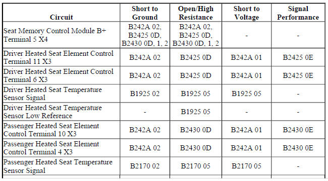
- Ignition OFF, disconnect the X4 harness connector at the K40 Seat Memory Control Module, ignition ON.
- Verify a test lamp illuminates between the B+ circuit terminal 5 and ground.
- If the test lamp does not illuminate
- Ignition OFF.
- Test for infinite resistance between the B+ circuit and ground.
- If less than infinite resistance, repair the short to ground on the circuit.
- If infinite resistance
- Test for less than 2 ohms in the B+ circuit end to end.
- If 2 ohms or greater, repair the open/high resistance in the circuit.
- If less than 2 ohms, verify the fuse is not open and there is voltage at the fuse.
- If the test lamp illuminates
- Ignition OFF, connect the X4 harness connector at the K40 Seat Memory Control Module and disconnect the harness connector at the E14A Seat Heating Element - Driver Back.
NOTE: Element resistance must be measured twice to ensure that all failure conditions are simulated. First with the seat unoccupied, then with the seat occupied.
- Test for 0.5-2.0 ohms between control circuit terminal A and control circuit terminal B.
- If not between 0.5-2.0 ohms
Replace the E14A Seat Heating Element - Driver Back.
- If between 0.5-2.0 ohms
- Connect the harness connector at the E14A Seat Heating Element - Driver Back and disconnect the X3 harness connector at the K40 Seat Memory Control Module.
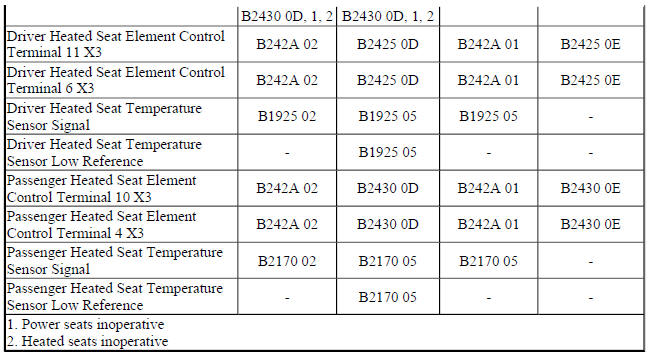
- Test for 1-5 ohms between control circuit terminal 11 and control circuit terminal 6.
- If less than 1 ohms
- Ignition OFF, disconnect the harness connector at the E14B Seat Heating Element - Driver Cushion.
- Test for infinite resistance between the control circuits.
- If less than infinite resistance, repair the short between the circuits.
- If infinite resistance, test or replace the E14B Seat Heating Element - Driver Cushion.
- If greater than 5 ohms
- Ignition OFF, disconnect the harness connector at the E14B Seat Heating Element - Driver Cushion.
- Test for less than 2 ohms in the control circuits end to end.
- If 2 ohms or greater, repair the open/high resistance in the circuit.
- If less than 2 ohms, test or replace the E14B Seat Heating Element - Driver Cushion.
- If between 1-5 ohms
- Replace the K40 Seat Memory Control Module.
B2430 0B, B2430 0D, or B2430 0E
- Ignition OFF, disconnect the X4 harness connector at the K40 Seat Memory Control Module, ignition ON.
- Verify a test lamp illuminates between the B+ circuit terminal 5 and ground.
- If the test lamp does not illuminate
- Ignition OFF.
- Test for less than 2 ohms in the B+ circuit end to end.
- If 2 ohms or greater, repair the open/high resistance in the circuit.
- If less than 2 ohms, verify the fuse is not open and there is voltage at the fuse.
- If the test lamp illuminates
- Ignition OFF, connect the X4 harness connector at the K40 Seat Memory Control Module and disconnect the harness connector at the E14C Seat Heating Element - Passenger Back.
NOTE:
Element resistance must be measured twice to ensure that all failure conditions are simulated. First with the seat unoccupied, then with the seat occupied.
- Test for 0.5-2.0 ohms between control circuit terminal A and control circuit terminal B.
- If not between 0.5-2.0 ohms
Replace the E14C Seat Heating Element - Passenger Back.
- If between 0.5-2.0 ohms
- Connect the harness connector at the E14C Seat Heating Element - Passenger Back and disconnect the X3 harness connector at the K40 Seat Memory Control Module.
- Test for 1-5 ohms between control circuit terminal 10 and control circuit terminal 4.
- If less than 1 ohms
- Ignition OFF, disconnect the harness connector at the E14D Seat Heating Element - Passenger Cushion.
- Test for infinite resistance between the control circuits.
- If less than infinite resistance, repair the short between the circuits.
- If infinite resistance, test or replace the E14D Seat Heating Element - Passenger Cushion.
- If greater than 5 ohms
- Ignition OFF, disconnect the harness connector at the E14D Seat Heating Element - Passenger Cushion.
- Test for less than 2 ohms in the control circuits end to end.
- If 2 ohms or greater, repair the open/high resistance in the circuit.
- If less than 2 ohms, test or replace the E14D Seat Heating Element - Passenger Cushion.
- If between 1-5 ohms
- Replace the K40 Seat Memory Control Module.
Repair Instructions
Perform the Diagnostic Repair Verification after completing the repair.
- Driver or Passenger Seat Back Cushion Heater Replacement
- Driver or Passenger Seat Cushion Heater Replacement
- Control Module References for K40 Seat Memory Control Module replacement, programming and setup
DTC B242A (WITHOUT MEMORY A45): Seat heaters common circuit
Diagnostic Instructions
- Perform the Diagnostic System Check - Vehicle prior to using this diagnostic procedure.
- Review Strategy Based Diagnosis for an overview of the diagnostic
approach.
Diagnostic Procedure Instructions provides an overview of each diagnostic category.
DTC Descriptors
DTC B242A 01
Seat Heaters Common Circuit Short to Battery
DTC B242A 02
Seat Heaters Common Circuit Short to Ground
Diagnostic Fault Information
Circuit/System Description
The seat heating control module controls the seat heating operation for both the driver and front passenger seats.
The module controls the heating element through individual high side and low side control circuits. The low side control circuits for both seats are connected to a common reference point internal to the module. This reference point is biased to approximately 2.5 V. Before the seat heating control module will allow heated seat operation, it checks to see if this biased voltage is shorted to ground or voltage. Once the module verifies that it is not closing to a shorted heating element, it allows for heated seat operation. The module then continues to monitor the heating elements for a shorted circuit.
Conditions for Running the DTC
- DTC B1325 must not be present.
- The seat heating control module must be powered.
Conditions for Setting the DTC
B242A 01
The seat heating control module detects a short to voltage on the heater element control circuits.
B242A 02
The seat heating control module detects a short to ground on the heater element control circuits.
Action Taken When the DTC Sets
The heated seat function for both seats will be disabled.
Conditions for Clearing the DTC
- The current DTC will clear and set a history code 3 s after the reference voltage returns to normal operating range and the ignition is cycled OFF then back to ACC or RUN.
- The history DTC will clear after 40 consecutive fault-free ignition cycles have occurred.
Reference Information
Schematic Reference
Heated/Cooled Seat Schematics (Encore), Heated/Cooled Seat Schematics (Encore)
Connector End View Reference
WIRING SYSTEMS AND POWER MANAGEMENT - COMPONENT CONNECTOR END VIEWS - INDEX - ENCORE WIRING SYSTEMS AND POWER MANAGEMENT - COMPONENT CONNECTOR END VIEWS - INDEX - Encore
Description and Operation
Heated Seats Description and Operation
Electrical Information Reference
- Circuit Testing
- Connector Repairs
- Testing for Intermittent Conditions and Poor Connections
- Wiring Repairs
Scan Tool Reference
Control Module References for scan tool information
Circuit/System Testing
- Ignition OFF, disconnect the X2 harness connector at the K29 Seat Heating Control Module.
- Test for infinite resistance between each control circuit terminal listed below and ground:
- Terminal 1
- Terminal 2
- If less than infinite resistance
Repair the short to ground on the circuit.
- If infinite resistance
- Ignition ON.
- Test for less than 1 V between the control circuit terminals listed below and ground:
- Terminal 1
- Terminal 2
- If 1 V or greater
Repair the short to voltage on the circuit.
- If less than 1 V
- Replace the K29 Seat Heating Control Module.
Repair Instructions
Perform the Diagnostic Repair Verification after completing the repair.
Control Module References for K29 Seat Heating Control Module replacement, programming and setup
DTC B242A (WITH MEMORY A45): Seat heaters common circuit
Diagnostic Instructions
- Perform the Diagnostic System Check - Vehicle prior to using this diagnostic procedure.
- Review Strategy Based Diagnosis for an overview of the diagnostic approach.
- Diagnostic Procedure Instructions provides an overview of each diagnostic category.
DTC Descriptors
DTC B242A 01
Seat Heaters Common Circuit Short to Battery
DTC B242A 02
Seat Heaters Common Circuit Short to Ground
Diagnostic Fault Information
Circuit/System Description
The seat memory control module controls seat heating operation for both the driver and front passenger seats.
The heating elements are controlled through individual high side and low side control circuits. The low side control circuits for both seats are connected to a common reference point internal to the module. This reference point is biased to approximately 2.5 V. Before the seat memory control module will allow heated seat operation, it checks to see if this biased voltage is shorted to ground or voltage. Once the module verifies that it is not closing to a shorted heating element, it allows for heated seat operation. The module will then continue to monitor the heating elements for a shorted circuit.
Conditions for Running the DTC
- DTC B1325 must not be present.
- The seat memory control module must be powered.
Conditions for Setting the DTC
B242A 01
The seat memory control module detects a short to voltage on the heater element control circuits.
B242A 02
The seat memory control module detects a short to ground on the heater element control circuits.
Action Taken When the DTC Sets
The heated seat function for both seats will be disabled.
Conditions for Clearing the DTC
- The current DTC will clear and set a history code 3 s after the reference voltage returns to normal operating range and the ignition is cycled OFF then back to ACC or RUN.
- The history DTC will clear after 40 consecutive fault-free ignition cycles have occurred.
Reference Information
Schematic Reference
Heated/Cooled Seat Schematics (Encore), Heated/Cooled Seat Schematics (Encore)
Connector End View Reference
WIRING SYSTEMS AND POWER MANAGEMENT - COMPONENT CONNECTOR END VIEWS - INDEX - ENCORE WIRING SYSTEMS AND POWER MANAGEMENT - COMPONENT CONNECTOR END VIEWS - INDEX - Encore
Description and Operation
Heated Seats Description and Operation
Electrical Information Reference
- Circuit Testing
- Connector Repairs
- Testing for Intermittent Conditions and Poor Connections
- Wiring Repairs
Scan Tool Reference
Control Module References for scan tool information
Circuit/System Testing
- Ignition OFF, disconnect the X4 harness connector at the K40 Seat Memory Control Module, ignition ON.
- Verify a test lamp illuminates between the B+ circuit terminal 5 and ground.
If the test lamp does not illuminate
- Ignition OFF.
- Test for infinite resistance between the B+ circuit and ground.
- If less than infinite resistance, repair the short to ground on the circuit.
- If infinite resistance
- Test for less than 2 ohms in the B+ circuit end to end.
- If 2 ohms or greater, repair the open/high resistance in the circuit.
- If less than 2 ohms, verify the fuse is not open and there is voltage at the fuse.
- If the test lamp illuminates
- Ignition OFF, connect the X4 harness connector at the K40 Seat Memory Control Module and disconnect the X3 harness connector at the K40 Seat Memory Control Module.
- Test for infinite resistance between the control circuit terminals listed below and ground:
- Terminal 11
- Terminal 10
- If less than infinite resistance
Repair the short to ground on the circuit.
- If infinite resistance
- Ignition ON.
- Test for less than 1 V between the control circuit terminals listed below and ground:
- Terminal 11
- Terminal 10
- If 1 V or greater
Repair the short to voltage on the circuit.
- If less than 1 V
- Replace the K40 Seat Memory Control Module.
Repair Instructions
Perform the Diagnostic Repair Verification after completing the repair.
Control Module References for K40 Seat Memory Control Module replacement, programming and setup
SYMPTOMS - SEAT HEATING AND COOLING
NOTE: The following steps must be completed before using the symptom tables.
- When diagnosing a heated seat system condition perform the Diagnostic System Check - Vehicle , before using the symptom tables in order to verify that all of the following are true:
- There are no DTCs set.
- The control module(s) can communicate via the serial data link.
- Review the system operation in order to familiarize yourself with the system functions. Refer to Heated Seats Description and Operation.
Visual/Physical Inspection
- Inspect for aftermarket devices which could affect the operation of the power seats. Refer to Checking Aftermarket Accessories .
- Inspect the easily accessible or visible system components for obvious damage or conditions which could cause the symptom.
- Inspect the seat adjuster track for conditions which may cause binding or objects within the seat adjustment range which obstruct movement or interfere with wiring.
Intermittent
Faulty electrical connections or wiring may be the cause of intermittent conditions. Refer to Testing for Intermittent Conditions and Poor Connections .
Symptom List
Refer to the Front Heated Seat Malfunction (Without Memory A45), Front Heated Seat Malfunction (With Memory A45) diagnostic procedure in order to diagnose the symptom.
Front heated seat malfunction (without memory A45)
Diagnostic Instructions
- Perform the Diagnostic System Check - Vehicle prior to using this diagnostic procedure.
- Review Strategy Based Diagnosis for an overview of the diagnostic approach.
- Diagnostic Procedure Instructions provides an overview of each diagnostic category.
Diagnostic Fault Information
Circuit/System Description
The driver and passenger heated seats are controlled by separate heated seat switches that are located in the HVAC control. When a heated seat switch is pressed, a serial data message is sent from the HVAC control module to the seat heating control module indicating the heated seat command. In response to this message, the seat heating control module applies battery positive voltage through the element supply voltage circuit to the appropriate seat heating elements. The seat heating control module then sends a serial data message back to the HVAC control module to either illuminate or turn off the appropriate temperature indicator.
Reference Information
Schematic Reference
Heated/Cooled Seat Schematics (Encore), Heated/Cooled Seat Schematics (Encore)
Connector End View Reference
WIRING SYSTEMS AND POWER MANAGEMENT - COMPONENT CONNECTOR END VIEWS - INDEX - ENCORE WIRING SYSTEMS AND POWER MANAGEMENT - COMPONENT CONNECTOR END VIEWS - INDEX - Encore
Description and Operation
Heated Seats Description and Operation
Electrical Information Reference
- Circuit Testing
- Connector Repairs
- Testing for Intermittent Conditions and Poor Connections
- Wiring Repairs
Scan Tool Reference
Control Module References for scan tool information
Circuit/System Verification
- Engine ON.
- Verify that no heated seat DTCs are set.
- If any heated seat DTC is set
Refer to Diagnostic Trouble Code (DTC) List - Vehicle
- If no heated seat DTCs are set
- Verify the scan tool Front Seat Heating Control Module Driver Seat Heating/Venting/Cooling Mode parameter changes between Off and Back & Cushion Heat after pressing the driver heated seat switch
- If the parameter does not change
Replace the K33 HVAC Control Module.
- If the parameter changes
- Verify the scan tool Passenger Front Seat Heating/Venting/Cooling Mode Switch parameter changes between Off and Back & Cushion Heat after pressing the passenger heated seat switch
- If the parameter does not change
Replace the K33 HVAC Control Module.
- If the parameter changes
- Replace the K29 Seat Heating Control Module.
Repair Instructions
Perform the Diagnostic Repair Verification after completing the repair.
Control Module References for K29 Seat Heating Control Module and K33 HVAC Control Module replacement, programming and setup
Front heated seat malfunction (with memory A45)
Diagnostic Instructions
- Perform the Diagnostic System Check - Vehicle prior to using this diagnostic procedure.
- Review Strategy Based Diagnosis for an overview of the diagnostic approach.
- Diagnostic Procedure Instructions provides an overview of each diagnostic category.
Diagnostic Fault Information
Circuit/System Description
The driver and front passenger heated seats are controlled by separate heated seat switches that are located in the radio/HVAC controls. When a heated seat switch is pressed, a serial message is sent from the radio/HVAC controls to the HVAC control module indicating the heated seat command. The HVAC control module then serves as a gateway to transmit the message to the seat memory control module via the serial data line. In response to this message, the seat memory control module applies battery positive voltage through the element supply voltage circuit to the appropriate seat heating elements. The seat memory control module then sends a serial data message back to the HVAC control module to gateway the information to the radio/HVAC controls to either illuminate or turn off the appropriate temperature indicator.
Reference Information
Schematic Reference
Heated/Cooled Seat Schematics (Encore), Heated/Cooled Seat Schematics (Encore)
Connector End View Reference
WIRING SYSTEMS AND POWER MANAGEMENT - COMPONENT CONNECTOR END VIEWS - INDEX - ENCORE WIRING SYSTEMS AND POWER MANAGEMENT - COMPONENT CONNECTOR END VIEWS - INDEX - Encore
Description and Operation
Heated Seats Description and Operation
Electrical Information Reference
- Circuit Testing
- Connector Repairs
- Testing for Intermittent Conditions and Poor Connections
- Wiring Repairs
Scan Tool Reference
Control Module References for scan tool information
Circuit/System Verification
- Engine ON.
- Verify that no heated seat DTCs are set.
- If any heated seat DTC is set
Refer to Diagnostic Trouble Code (DTC) List - Vehicle
- If no heated seat DTCs are set
- Verify the scan tool Front Seat Heating Control Module Driver Seat Heating/Venting/Cooling Mode parameter changes between Off and Back & Cushion Heat after pressing the driver heated seat switch.
- If the parameter does not change
Replace the K33 HVAC Control Module.
- If the parameter changes
- Verify the scan tool Passenger Front Seat Heating/Venting/Cooling Mode Switch parameter changes between Off and Back & Cushion Heat after pressing the passenger heated seat switch.
- If the parameter does not change
Replace the K33 HVAC Control Module.
- If the parameter changes
- Refer to Circuit/System Testing.
Circuit/System Testing
- Ignition OFF, disconnect the X4 harness connector at the K40 Seat Memory Control Module, ignition ON.
- Verify a test lamp illuminates between the B+ circuit terminal 5 and ground.
If the test lamp does not illuminate
- Ignition OFF.
- Test for less than 2 ohms in the B+ circuit end to end.
- If 2 ohms or greater, repair the open/high resistance in the circuit.
- If less than 2 ohms, verify the fuse is not open and there is voltage at the fuse.
- If the test lamp illuminates
- Ignition OFF, connect the X4 harness connector at the K40 Seat Memory Control Module, ignition ON,
- Verify the scan tool Seat Memory Control Module Driver Seat Heating/Venting/Cooling Mode parameter changes between Off and Back & Cushion Heat after pressing the driver heated seat switch.
- If the parameter does not change
Replace the A20 Radio/HVAC Controls.
- If the parameter changes
- Verify the scan tool Passenger Front Seat Heating/Venting/Cooling Mode parameter changes between Off and Back & Cushion Heat after pressing the passenger heated seat switch.
- If the parameter does not change
Replace the A20 Radio/HVAC Controls.
- If the parameter changes
- Replace the K40 Seat Memory Control Module.
Repair Instructions
Perform the Diagnostic Repair Verification after completing the repair.
- Radio Control Assembly Replacement
- Control Module References for K40 Seat Memory Control Module replacement, programming and setup
READ NEXT:
 Seat heating and cooling - Repair instructions
FRONT SEAT HEATER CONTROL MODULE REPLACEMENT
Fig. 3: Front Seat Heater Control Module
Front Seat Heater Control Module Replacement
DRIVER OR PASSENGER SEAT BACK CUSHION HEATER REPLACEMENT
Fig.
Seat heating and cooling - Description and operation
HEATED SEATS DESCRIPTION AND OPERATION
Heated Seat Components
The driver and passenger heated seats consist of the following components:
Left heated seat switch
Right heated seat switch
HVAC contr
Secondary and Configurable Customer Controls
Schematic wiring diagrams
STEERING WHEEL SECONDARY/CONFIGURABLE CONTROL WIRING SCHEMATICS
(ENCORE)
Steering Wheel Control System
Fig. 1: Steering Wheel Control System
STEERING WHEEL SECONDARY/CONFIG
SEE MORE:
Cabin Air Filter
REMOVAL & INSTALLATION
NOTE: Manufacturer's terminology for this filter is passenger
compartment air filter.
CABIN AIR FILTER
Removal & Installation
Fig. 1: Passenger Compartment Air Filter
Anti-Lock Brake Safety Precautions
PLEASE READ THIS FIRST *
This article is intended for general information purposes only. This
information may not apply to all makes and
models. If vehicle is equipped with Anti-Lock Brake System (ABS), refer to
appropriate ANTI-LOCK BRAKE
SYSTEM article in the BRAKES section for description, oper
