Buick Encore: Theft Deterrent - Diagnostic information and procedures
Symptoms - theft deterrent
NOTE: The following steps must be completed before using the symptom tables.
- Perform Diagnostic System Check - Vehicle in order to verify that all of the following are true:
- There are no DTCs set.
- The control modules can communicate via the serial data link.
- Review the system operation in order to familiarize yourself with the system functions. Refer to the following Theft Systems Description and Operation.
Visual/Physical Inspection
- Inspect for aftermarket devices which could affect the operation of the Theft Deterrent System. Refer to Checking Aftermarket Accessories .
- Inspect the easily accessible or visible system components for obvious damage or conditions which could cause the symptom.
Intermittent
Faulty electrical connections or wiring may be the cause of intermittent conditions. Refer to Testing for
Intermittent Conditions and Poor Connections .
Symptom List
Refer to a symptom diagnostic procedure from the following list in order to diagnose the symptom:
- Content Theft Deterrent Malfunction
- Security Indicator Malfunction
CONTENT THEFT DETERRENT MALFUNCTION
Diagnostic Instructions
- Perform the Diagnostic System Check - Vehicle prior to using this diagnostic procedure
- Review Strategy Based Diagnosis for an overview of the diagnostic approach.
- Diagnostic Procedure Instructions provides an overview of each diagnostic category.
Circuit/System Description
The content theft deterrent system is a software based system in which the Body Control Module (BCM) actively monitors certain inputs to determine if unauthorized vehicle access is being attempted. Based on inputs such as the door ajar switches, the rear compartment ajar switch, and the hood ajar switch, the BCM determines whether a content theft deterrent alarm is warranted. If unauthorized access is being detected, the BCM will pulse the vehicle horn and flash the exterior lamps as a means of theft deterrence.
Diagnostic Aids
The scan tool BCM Content Theft Deterrent Trigger History 1, 2, and 3 parameters can be used to help isolate an intermittent unwanted content theft deterrent alarm. These parameters are a rolling history of the previous three causes of a theft deterrent alarm. If all three parameters are indicating the same alarm trigger, the indicated input should be the starting point when diagnosing an intermittent concern.
Reference Information
Schematic Reference
Theft Deterrent System Schematics (Encore), Theft Deterrent System Schematics (Encore)
Connector End View Reference
WIRING SYSTEMS AND POWER MANAGEMENT - COMPONENT CONNECTOR END VIEWS - INDEX - ENCORE WIRING SYSTEMS AND POWER MANAGEMENT - COMPONENT CONNECTOR END VIEWS - INDEX - Encore
Description and Operation
Theft Systems Description and Operation
Electrical Information Reference
- Circuit Testing
- Connector Repairs
- Testing for Intermittent Conditions and Poor Connections
- Wiring Repairs
Scan Tool Reference
Control Module References for scan tool information
Circuit/System Verification
- Ignition ON.
- Verify each indicator/message transition between the ajar and closed state while opening and closing each vehicle door, hood, and rear compartment.
If the indicator/message does not change
Refer to Door Ajar Indicator Malfunction , or Hood Ajar Indicator/Message Malfunction
If each indicator/message changes
- Completely lower the driver door window and close all vehicle doors, ignition OFF.
- Arm the content theft deterrent system by locking the door with the keyless entry transmitter.
- Verify the scan tool BCM Content Theft Deterrent Alarm Status parameter is Armed.
If not Armed
Refer to Keyless Entry System Malfunction .
If Armed
- Without disarming the system, reach in through the open driver window and open the driver door.
- Verify the scan tool BCM Content Theft Deterrent Alarm Status parameter is Alarm.
If not Alarm
Replace the K9 Body Control Module.
If Alarm
- All OK.
Repair Instructions
Perform the Diagnostic Repair Verification after completing the repair.
Control Module References for Body Control Module replacement, programming, and setup
Security indicator malfunction
Diagnostic Instructions
- Perform the Diagnostic System Check - Vehicle prior to using this diagnostic procedure.
- Review Strategy Based Diagnosis for an overview of the diagnostic approach.
- Diagnostic Procedure Instructions provides an overview of each diagnostic category.
Diagnostic Fault Information
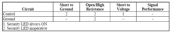
Circuit/System Description
The security LED is controlled by the Body Control Module (BCM) based on commands from the content theft deterrent system. The security LED is located in the instrument panel as part of the ambient light sensor and is supplied ground at all times. When the content theft deterrent system requests the LED be illuminated, the BCM applies voltage to the control circuit, illuminating the LED.
Reference Information
Schematic Reference
Theft Deterrent System Schematics (Encore), Theft Deterrent System Schematics (Encore)
Connector End View Reference
WIRING SYSTEMS AND POWER MANAGEMENT - COMPONENT CONNECTOR END VIEWS - INDEX - ENCORE WIRING SYSTEMS AND POWER MANAGEMENT - COMPONENT CONNECTOR END VIEWS - INDEX - Encore
Description and Operation
Theft Systems Description and Operation
Electrical Information Reference
- Circuit Testing
- Connector Repairs
- Testing for Intermittent Conditions and Poor Connections
- Wiring Repairs
Scan Tool Reference
Control Module References for scan tool information
Circuit/System Verification
- Arm the content theft deterrent system.
- Verify the security LED illuminates or flashes during the arming sequence.
If the security LED does not illuminate or flash
Refer to Circuit/System Testing
If the security LED illuminates or flashes
- All OK.
Circuit/System Testing
- Ignition OFF and all vehicle systems OFF, disconnect the harness
connector at the B104 Sunload Sensor.
It may take up to 2 minutes for all vehicle systems to power down.
- Test for less than 30 ohms between the ground circuit terminal 6 and ground.
If 30 ohms or greater
- Ignition OFF.
- Test for less than 2 ohms in the ground circuit end to end.
- If 2 ohms or greater, repair the open/high resistance in the circuit.
- If less than 2 ohms, repair the open/high resistance in the ground connection.
If less than 30 ohms
- Ignition ON, connect a test lamp between the control circuit terminal 1 and the ground circuit terminal 6.
- Verify the test lamp turns ON and OFF when commanding the Security Indicator On and Off with a scan tool.
If the test lamp is always OFF
- Ignition OFF, disconnect the harness connector at the K9 Body Control Module.
- Test for infinite resistance between the control circuit and ground.
- If less than infinite resistance, repair the short to ground on the circuit.
- If infinite resistance
- Test for less than 2 ohms in the control circuit end to end.
- If 2 ohms or greater, repair the open/high resistance in the circuit.
- If less than 2 ohms, replace the K9 Body Control Module.
If the test lamp is always ON
- Ignition OFF, disconnect the harness connector at the K9 Body Control Module, ignition ON.
- Test for less than 1 V between the control circuit and ground.
- If 1 V or greater, repair the short to voltage on the circuit.
- If less than 1 V, replace the K9 Body Control Module.
If the test lamp turns ON and OFF
- Test or replace the B104 Sunload Sensor.
Repair Instructions
Perform the Diagnostic Repair Verification after completing the repair.
- Sun Load Temperature Sensor Replacement
- Control Module References for Body Control Module replacement, programming, and setup
READ NEXT:
 Theft Deterrent - Description and operation
THEFT SYSTEMS DESCRIPTION AND OPERATION
When armed, the content theft deterrent system is designed to deter vehicle
content theft by pulsing the horns
and exterior lamps for approximately 30 seconds
Bumpers and Fascias
Repair instructions
SPECIFICATIONS
FASTENER TIGHTENING SPECIFICATIONS
Fastener Tightening Specifications
REPAIR INSTRUCTIONS
FRONT BUMPER FASCIA ENERGY UPPER ABSORBER REPLACEMENT
Fig. 1: Front Bum
Cruise Control
Schematic wiring diagrams
Cruise control system wiring schematics (ENCORE)
Cruise Control
Fig. 1: Cruise Control System Wiring Schematic
CRUISE CONTROL SYSTEM WIRING SCHEMATICS (Encore)
Cruise Contr
SEE MORE:
Remote Functions - Diagnostic information and procedures
SCHEMATIC WIRING DIAGRAMS
REMOTE FUNCTION WIRING SCHEMATICS (ENCORE)
Keyless Entry System
Fig. 1: Keyless Entry System (Encore)
REMOTE FUNCTION WIRING SCHEMATICS (Encore)
Keyless Entry System
Fig. 1: Keyless Entry System (Encore)
REMOTE FUNCTION WIRING SCHEMATICS (Encore)
Keyless Entry System
Lap-Shoulder Belt
All seating positions in the vehicle
have a lap-shoulder belt.
The following instructions explain
how to wear a lap-shoulder belt
properly.
Adjust the seat, if the seat is
adjustable, so you can sit up
straight. To see how, see
"Seats" in the Index.
Pick up the latch plate and pull
the b
